Electronic Project 31: A simple guide on how to use Humidity –Temperature sensor as a rain sensing device with a buzzer alarm
What Will I Learn?
At the end of this tutorial:
♦ The readers will be able to create a circuit using the humidity – temperature sensor in detecting rain
♦ The readers will be able to know how the circuit works.
♦ Learn to apply the circuit in the future electronic projects
Introduction
In this tutorial, we will know how to use the humidity –temperature sensor in sensing rain. You can use this rain sensing circuit in your future electronic projects that needs the function of this circuit. When there is rain, a sound signal or a light signal will be displayed.
You can read more about Humidity –Temperature Sensor Here

Requirements
Electronic Components
♦ Arduino Uno
♦ Humidity – Temperature Sensor
♦ Resistor
♦ Transistor
♦ LED
♦ Buzzer/Speaker
♦ Breadboard
♦ Connecting wires
Software
♦ Fritzing application
Difficulty
♦ Advance
Tutorial Contents
Using the fritzing software, we will create our circuit diagram, arduino codes and prototype using the breadboard
Part I. Schematic Diagram
So first let us construct our circuit diagram.

Select the electronic components needed for the circuit in the fritzing library. We need 1 arduinouno, 1 Humidity Temperature Sensor, 1 LED, 1 Buzzer, 1 transistor, 1 buzzer and 4 resistors.

Arrange the components before constructing the circuit.
In arranging the components, place all the components for the input side (left side) of the arduino and the components for the output side (right side).
In this tutorial the input component will be the humidity –temperature sensor that will be connected to our microcontroller.

Now let us construct our circuit diagram.
At the input side of our circuit, we have the humidity temperature sensor. This sensor has three pins, 1 for source voltage, one for the output data signal and for ground terminal. So we will connect these three respectively, source voltage from the arduino, data signal for pin A2 and resistor directed to the ground.

While at the output side of our circuit, we have the pin output number 13. This pin will be connected to our amplifier circuit as an input signal. We need to amplify the output signal so that it can drive our external circuit.

Our external circuit is consist of an LED in series with the led and connected it to a buzzer in a parallel connection. We need to put a series resistor to the led in order to limit the flow of current and to avoid damaging the led.
Then the amplified output at the collector terminal will be connected to our external circuit as an input signal.
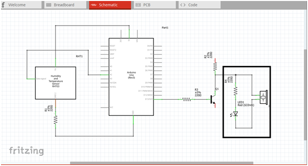
Now this is our final circuit diagram.

When the humidity sensor triggers or when there is rain, or a water drop, it will send data signal to the input pin of our microcontroller. Make sure that the sensor will be placed outside where it can be easily exposed or hit when there is rain.

This data signal will now triggers the microcontroller to give output at pin 13 based from our programmed codes. This output signal is then fed to the amplifier circuit to be amplified.

The amplified signal at the collector terminal is connected to the external circuit as input. Our external circuit is the led and the buzzer that is connected in parallel. The amplified signal will drive this circuit allowing led to give lights and the buzzer to give sound.

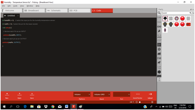
Part II. Code
Now let us do programming of our Arduinouno.
Click on code to start.

The input pin for our microcontroller from the humidity sensor is analog pin 2 and the output pin is 13.
inthumidPin = ;   // select the input pin for the humidity-temperature sensor
intresPin = 13; // select the pin for the base resistor

void setup() {
  // declare each Pin as an INPUT:
pinMode(humidPin, INPUT);
// declare each pin as an OUTPUT:
pinMode(resPin, OUTPUT);
}
int rain = 0; //initial value when there is rain

void loop() {
  // read the humidity sensor  and store it in the variable rain
rain = digitalRead(humidPin);
if(rain == 1)
//when there is no rain
digitalWrite(resPin, LOW);
//delay 1 second
delay(1000);
//when there is rain
if (rain == 0)
digitalWrite(resPin, HIGH);
//delay 1 second
delay(1000);
}

Here are our arduino codes.
inthumidPin = 2;   // select the input pin for the humidity-temperature sensor
intresPin = 13; // select the pin for the base resistor
void setup() {
  // declare each Pin as an INPUT:
  pinMode(humidPin, INPUT);
// declare each pin as an OUTPUT:
pinMode(resPin, OUTPUT);
}
int rain = 0; //initial value when there is rain
intmeasuredvalue = 0; //measured value when there is rain
void loop() {
  // read the humidity sensor  and store it in the variable rain
rain = digitalRead(humidPin);
if(rain == 1)
//when there is no rain
digitalWrite(resPin, LOW);
//delay 1 second
delay(1000);
//when there is rain
if (rain == 0)
digitalWrite(resPin, HIGH);
//delay 1 second
delay(1000);
}
Part III. Breadboard
Click on the breadboard.

Arrange each component in the breadboard before connecting.

Now connect each component if you don’t know how to connect using breadboard just read my previous tutorial about how to construct a circuit in the breadboard

Application
The readers can create their own rain detection circuit or can make a project that needs the functionality of this circuit like this example below.
Curriculum
Here are my other tutorials for electronic projects.
ELECTRONIC PROJECTS
Posted on Utopian.io - Rewarding Open Source Contributors
Thank you for the contribution. It has been approved.
You can contact us on Discord.
[utopian-moderator]
thanks @cha0s0000
Hey @rfece143 I am @utopian-io. I have just upvoted you!
Achievements
Community-Driven Witness!
I am the first and only Steem Community-Driven Witness. Participate on Discord. Lets GROW TOGETHER!
Up-vote this comment to grow my power and help Open Source contributions like this one. Want to chat? Join me on Discord https://discord.gg/Pc8HG9x