Electronic Project 25: Audio Volume Control and Light dimmer using potentiometer and arduino uno
What Will I Learn?
At the end of this tutorial:
♦ The readers will be able to create a light dimmer circuit that can be used in the house
♦ The readers will be able to know how the circuit works.
♦ Learn to apply the circuit in making electronic projects and its application to the industry
Introduction
Today, we will create a simple light dimmer circuit using a potentiometer and arduino uno. The brightness of a light is being controlled by the potentiometer. At the same time, the audio volume can be minimized using the potentiometer as what we know/see from most radio equipment.
What is a potentiometer?
This is a three terminal resistor with a rotating mechanism that forms an adjustable voltage divider. If only two terminals used, it is called rheostat.
You can read more here
Requirements
Electronic Components
♦ Arduino Uno
♦ Potentiometer
♦ LED
♦ Speaker /Piezo speaker
♦ Resistor
♦ Transistor
♦ Breadboard
♦ Connecting wires
Software
♦ Fritzing application
Difficulty
♦ Advance
Tutorial Contents
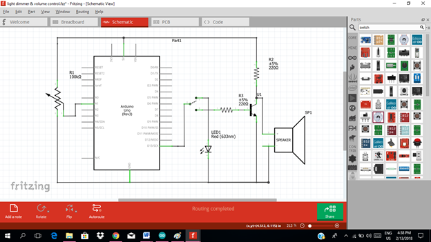
Using the fritzing software, we will create our circuit diagram, arduino codes and prototype using the breadboard
Part I. Schematic Diagram
So first let us construct our circuit diagram.
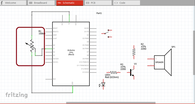
Select the electronic components needed for the circuit in the fritzing library. We need 1 arduino uno, 1 potentiometer, 3 resistors, 1 led, 1 speaker, 1 toggle switch and 1 transistor.
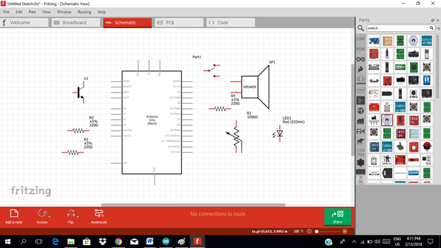
Arrange the components before constructing the circuit.
In arranging the components, place all the components for the input side (left side) of the arduino and the components for the output side (right side).
In this tutorial the input components will be the potentiometer. The rest of the components are for the output side.
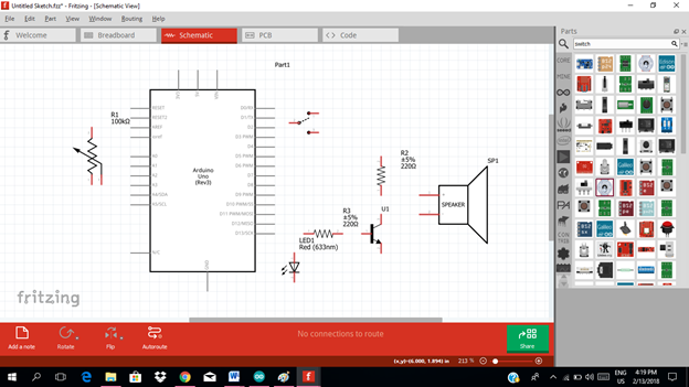
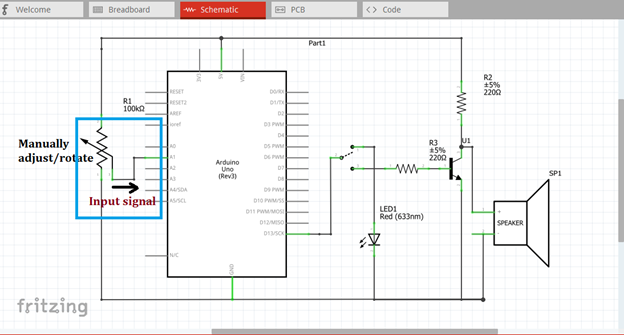
Now let us construct our circuit diagram. The input of our microcontroller will be the potentiometer that is used to control the volume of the speaker and dimming the light of the led.
We will choose the analog pin input of our microcontroller, for this tutorial I will use the analog pin 1. The middle terminal of the potentiometer will be connected to this input pin. Then the other terminal will be connected to the source voltage as input then the other one to the ground.
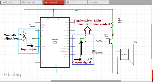
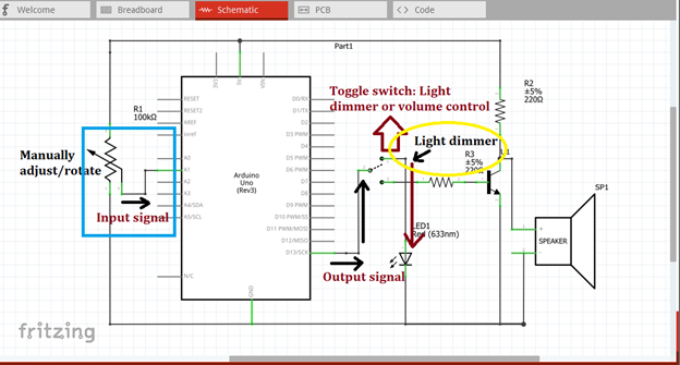
Then at the output side of our microcontroller, we need only 1 output pin, so I will use the pin 13. This pin 13 will be connected to the toggle switch. The toggle switch serves as controller in which component we want to control, light dimmer for led or volume control for the speaker.
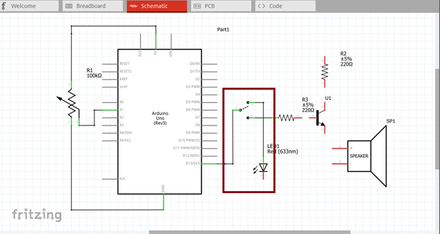
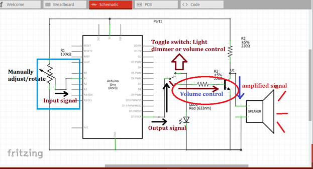
The switch has two terminals, one terminal is connected to the led and the other for the amplifier circuit as input. We will connect the output of the amplifier circuit to the speaker. Although we can control directly the speaker by putting a potentiometer to the output of the amplifier circuit
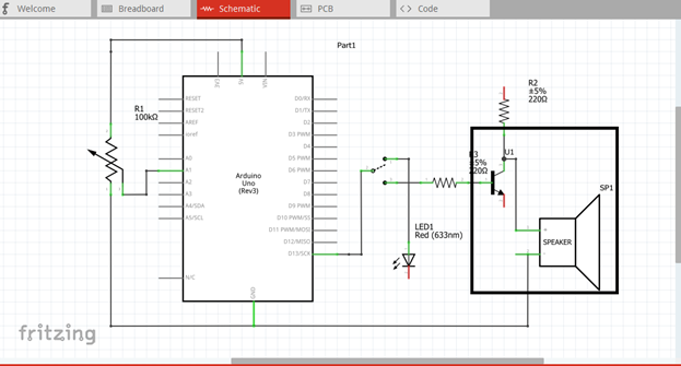
Here is our final circuit diagram.
In order to control the led brightness and the audio volume, we must manually adjust the potentiometer by rotating it. Then there is a input current that will flow through the pin 1.
Since our arduino is programmed to give output at pin 13 the moment the potentiometer is being adjusted and there is a current input. The output signal at pin 13 is being fed to the toggle switch. We can select which operation we want, either light dimmer or volume control.
If we select the light dimmer operation, the potentiometer will control the brightness of the led by adjusting it to our desired brightness.
While if we select the volume control operation, the input signal to the base terminal of the transistor will be minimized allowing small current to flow upon adjusting the potentiometer. Now there will be a small amplified signal that will drive the speaker. That’s the time the volume is being control.
Part II. Code
Now let us do programming of our Arduino uno.
Click on code to start.
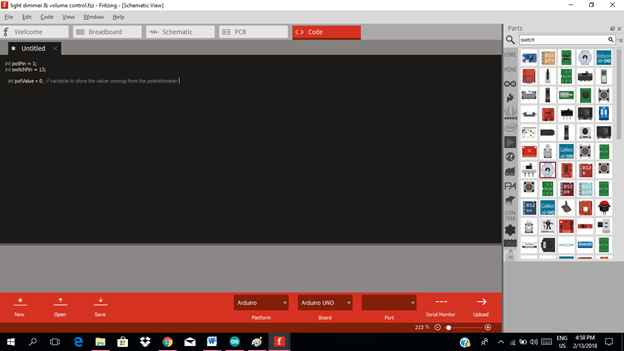
The input of our circuit is the potentiometer, so we must declare what pin it is and also the output pin in which we used pin 13.
int potPin = 1;   // select the input pin for the potentiometer
int switchPin = 13; // select the pin for the switch

int potValue = 0; // variable to store the value coming from the potentiometer
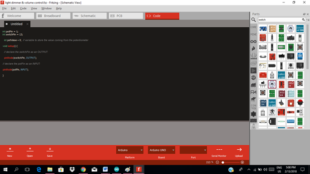
void setup() {
  // declare the switchPin as an OUTPUT:
  pinMode(switchPin, OUTPUT);
// declare the potPin as an INPUT:
pinMode(potPin, INPUT);
}
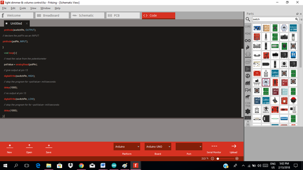
void loop() {
  // read the value from the potentiometer
  potValue = analogRead(potPin);
  // give output at pin 13
  digitalWrite(switchPin, HIGH);
  // stop the program for <potValue> milliseconds:
  delay(1000);
  // no output at pin 13
  digitalWrite(switchPin, LOW);
  // stop the program for for <potValue> milliseconds:
  delay(1000);
}
Here are our arduino codes.
int potPin = 1;
int switchPin = 13;
  int potValue = 0;  void setup() {
  pinMode(switchPin, OUTPUT);
pinMode(potPin, INPUT);
}
  void loop() {
  potValue = analogRead(potPin);
  digitalWrite(switchPin, HIGH);
  delay(1000);
   digitalWrite(switchPin, LOW);
   delay(1000);
}
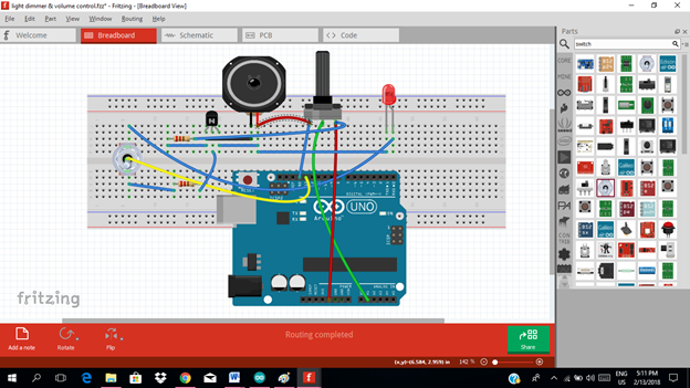
Part III. Breadboard
Click on the breadboard.
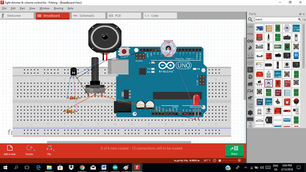
Arrange each component in the breadboard before connecting.
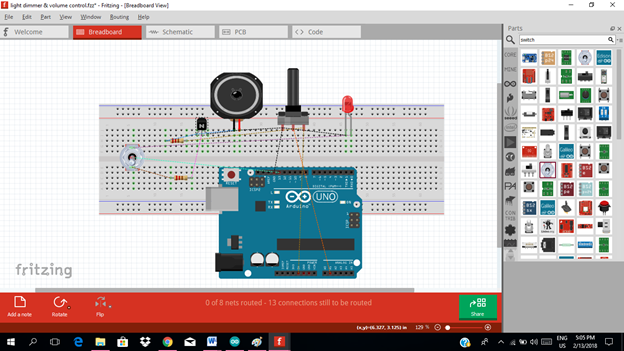
Now connect each component if you don’t know how to connect using breadboard just read my previous tutorial about how to construct a circuit in the breadboard

Application
The readers can create their own light dimming circuit and volume control using potentiometer.
Like the example below.
Curriculum
Here are my other tutorials for electronic projects.
ELECTRONIC PROJECTS
Posted on Utopian.io - Rewarding Open Source Contributors
thanks for sharing
your welcome ..i hope you find it helpful
Thank you for the contribution. It has been approved.
You can contact us on Discord.
[utopian-moderator]
Hey @rfece143 I am @utopian-io. I have just upvoted you!
Achievements
Suggestions
Get Noticed!
Community-Driven Witness!
I am the first and only Steem Community-Driven Witness. Participate on Discord. Lets GROW TOGETHER!
Up-vote this comment to grow my power and help Open Source contributions like this one. Want to chat? Join me on Discord https://discord.gg/Pc8HG9x