Electronic Project 12: Automatic Lights On & Off when sounds detected using Arduino Uno
What Will I Learn?
At the end of this tutorial:
The readers will be able to create an automatic switch on & off the lights for their rooms or inside the house and also an automatic door open and close using a solenoid or other mechanisms.
Requirements
**Electronic Components **
♦ Arduino Uno
♦ Piezo speaker
♦ Resistor
♦ Relay
♦ Led
♦ Transistor
♦ Breadboard
♦ Connecting wires
Software
♦ Fritzing application
Difficulty
♦ Advance
Tutorial Contents
Using the fritzing software, we will create our circuit diagram, arduino codes and prototype using the breadboard
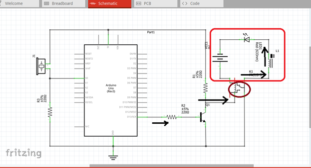
Part I. Schematic Diagram
So first let us construct our circuit diagram.
- Open the fritzing software and click on schematic.
- Select the electronic components needed for the circuit in the fritzing library. We need 1 arduino uno, 1 piezo speaker, 3 resistors, 1 battery, 1 transistor, 1 LED, 1 solenoid & 1 5V relay.
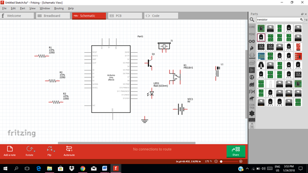
- Arrange the components before constructing the circuit.
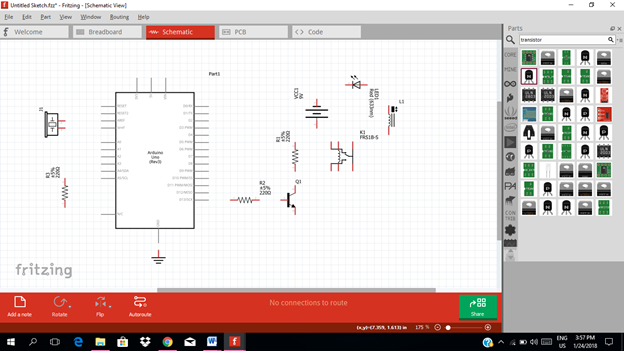
- Connect the circuit. At the input side of the circuit, connect the piezo speaker terminal to 5V source and the other terminal will be connected to analog input pin A0.

The resistor is connected through the ground. At the output side of our circuit, we will get the output at digital pin 13. This output is then fed to the base resistor of the transistor.


Then this output signal from pin 13 will be amplified by the transistor. The amplified signal from the collector terminal of the transistor is then connected to the input terminal of the 5V relay.

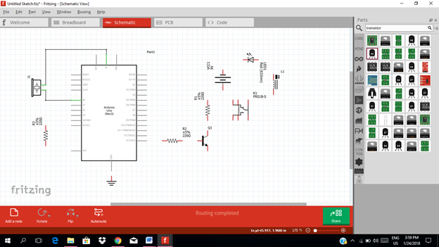
The output of the relay is then connected to the source battery which is the source of the LED and solenoid circuit.

This is our final circuit diagram.

A Piezo speaker is an electronic device that can both be used to play tones and to detect tones. In this project, a Piezo captures a knock and sends a signal to the arduino uno to give output on pin 13.
When the piezo speaker detects sound or a knock, it will triggers the arduino uno through the analog input pin A0.

At the output pin 13, the signal is then connected to amplifier circuit to be amplified to a certain level before connecting to the 5V relay.

The relay will triggers, and act as a close switch, allowing a current to flow through the solenoid and LED to lights on. This time the solenoid and LED will operate through the source battery.
Part II. Code
Now let us do programming of our Arduino uno.
Click on code to start.

The input of our arduino is coming from the piezo speaker whether it detects sounds or not. Then the output will be at the transistor base resistor. So we declare the pin input and pin output.
The threshold value is set to decide whether the sound detected is a clap or not.
int piezoPin = 0;
int resistorPin = 13;
int thresholdValue = 100;

Initial value of the sensor and the output value at pin 13. The resistorState is the variable used to store the last pin output status, to toogle the output.
Init piezoReading = 0;
Int resistorState = LOW;

We must declare the pin output and use of the serial port
void setup() {
pinMode(resistorPin, OUTPUT);
Serial.begin(9600); }
Void loop(){
piezoReading = analogRead(piezoPin);   //read the sensor and store it in the variable piezoReading
if(piezoReading >=thresholdValue){    //if it is greater than the thresholdvalue
resistorState =!resistorState;        //toggle the resistor status input
digitalWrite(resistorPin,resistorState); //send the string sound back to the computer
Serial.printIn(“Sound”);
} delay(100)
}

Here are the arduino codes.
int piezoPin = 0;
int resistorPin = 13;
int thresholdValue = 100;
init piezoReading = 0;
int resistorState = LOW;
void setup() {
pinMode(resistorPin, OUTPUT);
Serial.begin(9600);
} Void loop(){
piezoReading = analogRead(piezoPin);   piezoReading
 if(piezoReading >=thresholdValue){
resistorState =!resistorState;
digitalWrite(resistorPin,resistorState); Serial.printIn(“Sound”);
} delay(100)
}
Part III. Breadboard
Click on the breadboard.

Arrange each component in the breadboard before connecting.

Now connect each component if you don’t know how to connect using breadboard just read my previous tutorial about how to construct a circuit in the breadboard

Application
The readers can create their own clap switch mechanism in controlling lights, close/open doors & windows .
link source
Curriculum
Here are my other tutorials for electronic projects.
**ELECTRONIC PROJECTS **
Tutorial 1
Tutorial 2
Tutorial 3
Tutorial 4
Tutorial 5
Tutorial 6
Tutorial 7
Tutorial 8
Tutorial 9
Tutorial 10
Tutorial 11
Posted on Utopian.io - Rewarding Open Source Contributors
wow! my younger brother( an electronic geek) must see this, though i have little interest in electric and haven studied physics in the university my passion is where i want it to be: Organic Farming
wow @botefarm ..i hope your brother will like this..
I will be featuring it in my weekly #technology curation post for the @minnowsupport project and the Tech Bloggers' Guild! TBG is a new group of Steem tech bloggers and content creators looking to improve the overall quality of the niche.
If you wish to not be featured in the curation post this Saturday please let me know. Keep up the hard work and I hope to see you at the Tech Bloggers' Guild!
that would be awesome :-).. @jrswab ..thanks for that..yes you can..
Thank you for the contribution. It has been approved.
You can contact us on Discord.
[utopian-moderator]
thank you @forkonti