Stepper motor + Driver Uln2003 in arduino
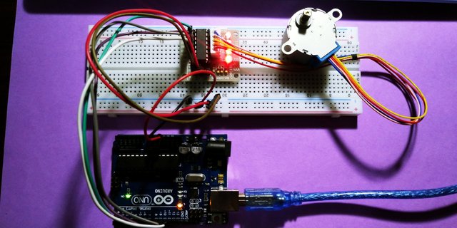
In this article I Will Show You How To Drive Stepper Motor With Arduino, I have a stepper motor with motor driver Uln2003 The rotation angle of this motor is proportional to the input pulse and this motor has full torque at standstill(if the windings are energized) Precise positioning and movement since stepper motors have an accuracy of – 5% of a step just like the cheap stepper motors out there, Since i have the driver for the motor it is easy to make a circuit on it.
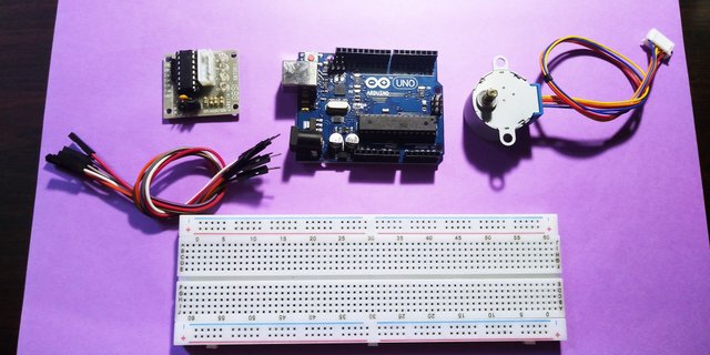
COMPONENTS NEEDED
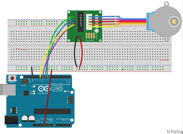
Using a breadboard here is optional, beacause theres only 2 wires will be connected on it the 5V and the GND of the motor, so i connect it directly to the arduino board.
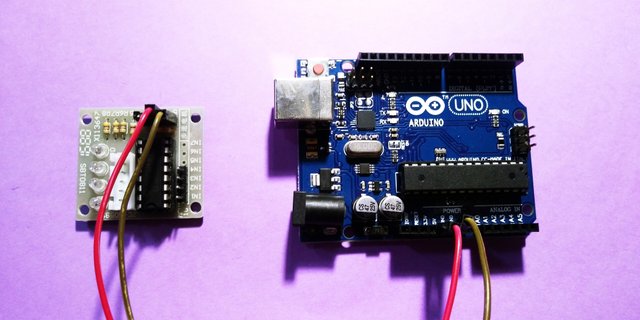
Connect the + sign on the motor driver to the 5V and the - to the GND on the arduino board
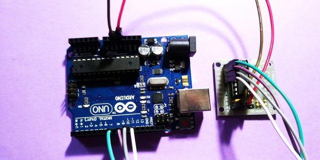
Connect all the IN pins to the digital pins on the arduino, theres only 4 pin so IN1 to the 8, IN2 to 9, IN3 to 10, and the IN4 to the digital pin 11, so thats the circuit.
SOFTWARE
Before we work on our sketch, make sure to download the Arduino IDE for your specific operating system. I’ll leave a link to where you can download this software: https://www.arduino.cc/en/Main/Software

Arduino Sketch code for Stepper motor;
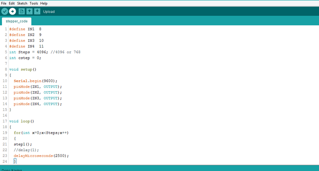
Copy the CODE here:
#define IN1 8#define IN2 9#define IN3 10#define IN4 11int Steps = 4096; //4096 or 768int cstep = 0;
void setup(){ Serial.begin(9600); pinMode(IN1, OUTPUT); pinMode(IN2, OUTPUT); pinMode(IN3, OUTPUT); pinMode(IN4, OUTPUT); }
void loop(){ for(int x=0;x<Steps;x++) { step1(); //delay(1); delayMicroseconds(2500); } Serial.println("Boom!!"); delay(1000); }
void step1(){ //stepp switch(cstep) { case 0: digitalWrite(IN1, LOW); digitalWrite(IN2, LOW); digitalWrite(IN3, LOW); digitalWrite(IN4, HIGH); break; case 1: digitalWrite(IN1, LOW); digitalWrite(IN2, LOW); digitalWrite(IN3, HIGH); digitalWrite(IN4, HIGH); break; case 2: digitalWrite(IN1, LOW); digitalWrite(IN2, LOW); digitalWrite(IN3, HIGH); digitalWrite(IN4, LOW); break; case 3: digitalWrite(IN1, LOW); digitalWrite(IN2, HIGH); digitalWrite(IN3, HIGH); digitalWrite(IN4, LOW); break; case 4: digitalWrite(IN1, LOW); digitalWrite(IN2, HIGH); digitalWrite(IN3, LOW); digitalWrite(IN4, LOW); break; case 5: digitalWrite(IN1, HIGH); digitalWrite(IN2, HIGH); digitalWrite(IN3, LOW); digitalWrite(IN4, LOW); break; case 6: digitalWrite(IN1, HIGH); digitalWrite(IN2, LOW); digitalWrite(IN3, LOW); digitalWrite(IN4, LOW); break; case 7: digitalWrite(IN1, HIGH); digitalWrite(IN2, LOW); digitalWrite(IN3, LOW); digitalWrite(IN4, HIGH); break; default: digitalWrite(IN1, LOW); digitalWrite(IN2, LOW); digitalWrite(IN3, LOW); digitalWrite(IN4, LOW); break; } cstep=cstep+1; if(cstep==8) {cstep=0;}}Connect the arduino uno to your computer then verify compile then upload it to the board. so this is the result.
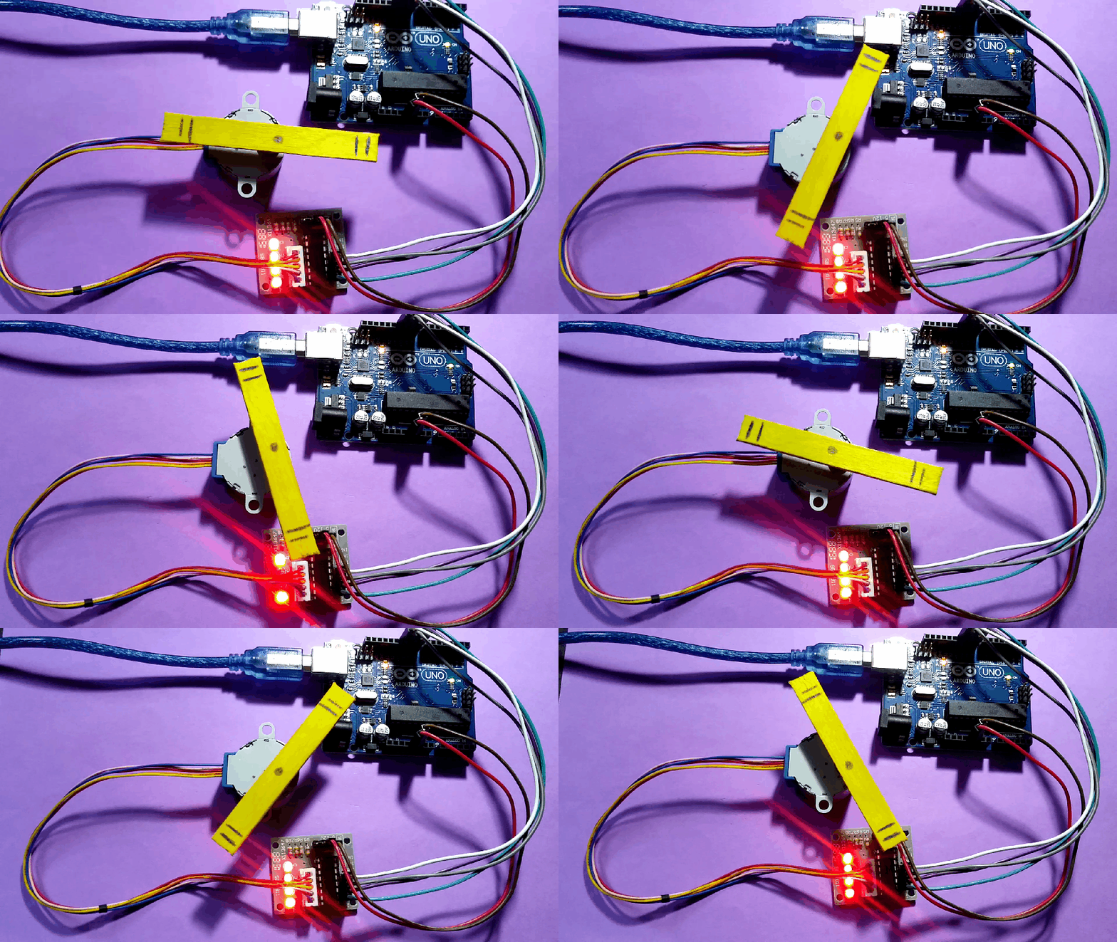
So thats it! if you wan to know how to program arduino this blog by the way i was inspired by the circuit here i just make some changes on the circuit bcoz its seems like the 5v and GND is connected to the same rail on the breadboard, i hope this post might help you thank you for passing by, please follow me @pakganern
![20180105_182452[1].jpg](https://steemitimages.com/640x0/https://res.cloudinary.com/hpiynhbhq/image/upload/v1515411279/xxxy5qsvmzodqfiglelf.jpg)
Posted on Utopian.io - Rewarding Open Source Contributors
Thank you for the contribution. It has been approved.
Example:
You can contact us on Discord.
[utopian-moderator]
noted thanks
Hey @pakganern I am @utopian-io. I have just upvoted you!
Achievements
Suggestions
Get Noticed!
Community-Driven Witness!
I am the first and only Steem Community-Driven Witness. Participate on Discord. Lets GROW TOGETHER!
Up-vote this comment to grow my power and help Open Source contributions like this one. Want to chat? Join me on Discord https://discord.gg/Pc8HG9x