LED Sequential Control- Arduino
Today I am going to show you guys a very simple arduino project for beginners. We’re going to get 2 different LEDs to turn on and turn off in a simple sequence, like you see in the gif below.
PARTS NEEDED
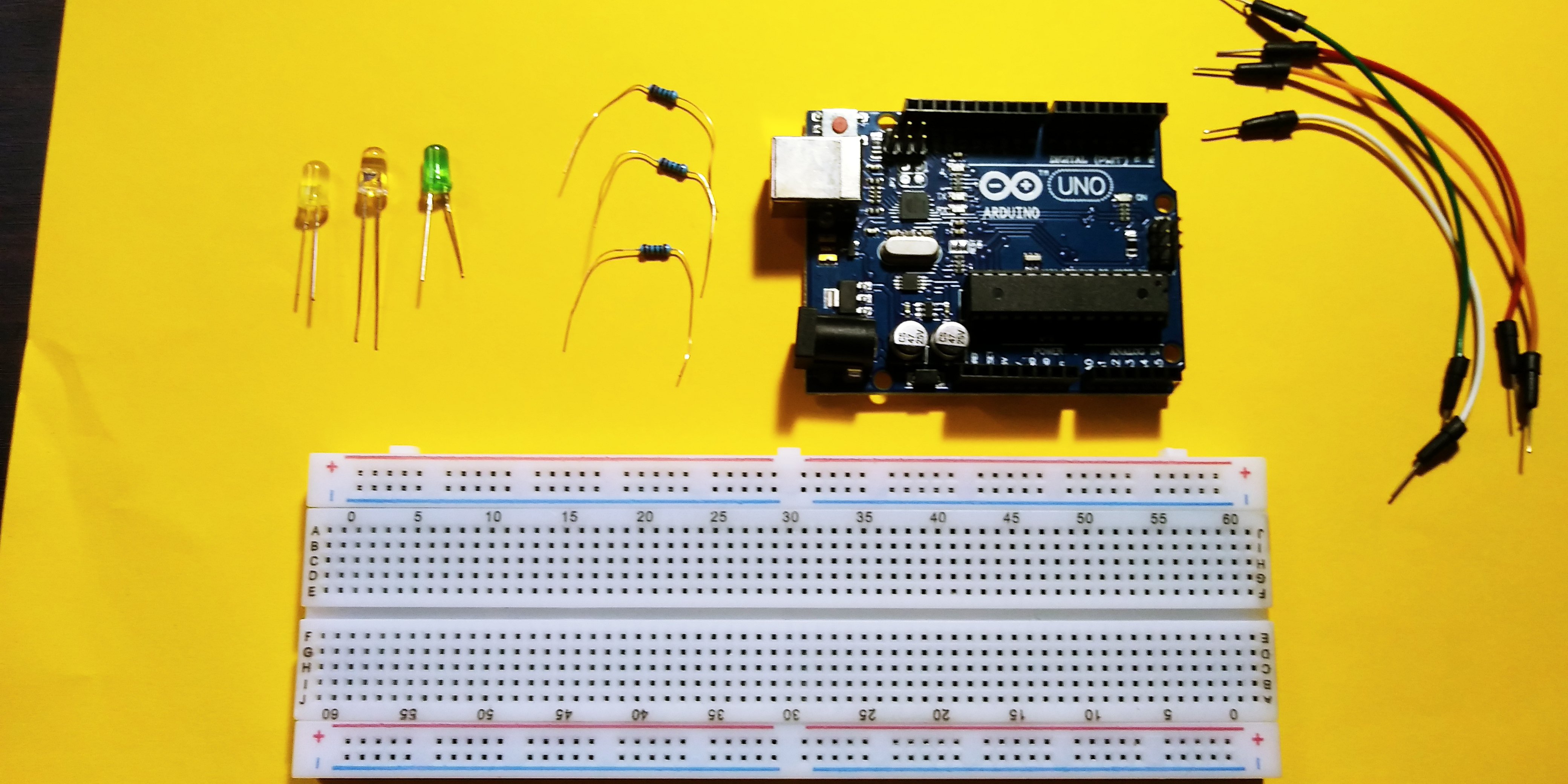
For this, you’re going to need an Arduino Uno, a breadboard (preferably with a positive and negative rail like this one), male to male jumper wires, a USB type B cable to for the Uno, LEDs of different colors and 220ohm resistors.

So lets first setup the hardware. The first step is to establish a common ground. To do this, use a jumper wire to connect the Ground pin on the arduino to the negative rail on the breadboard. This allows all the LEDs to use the ground pin on the arduino.
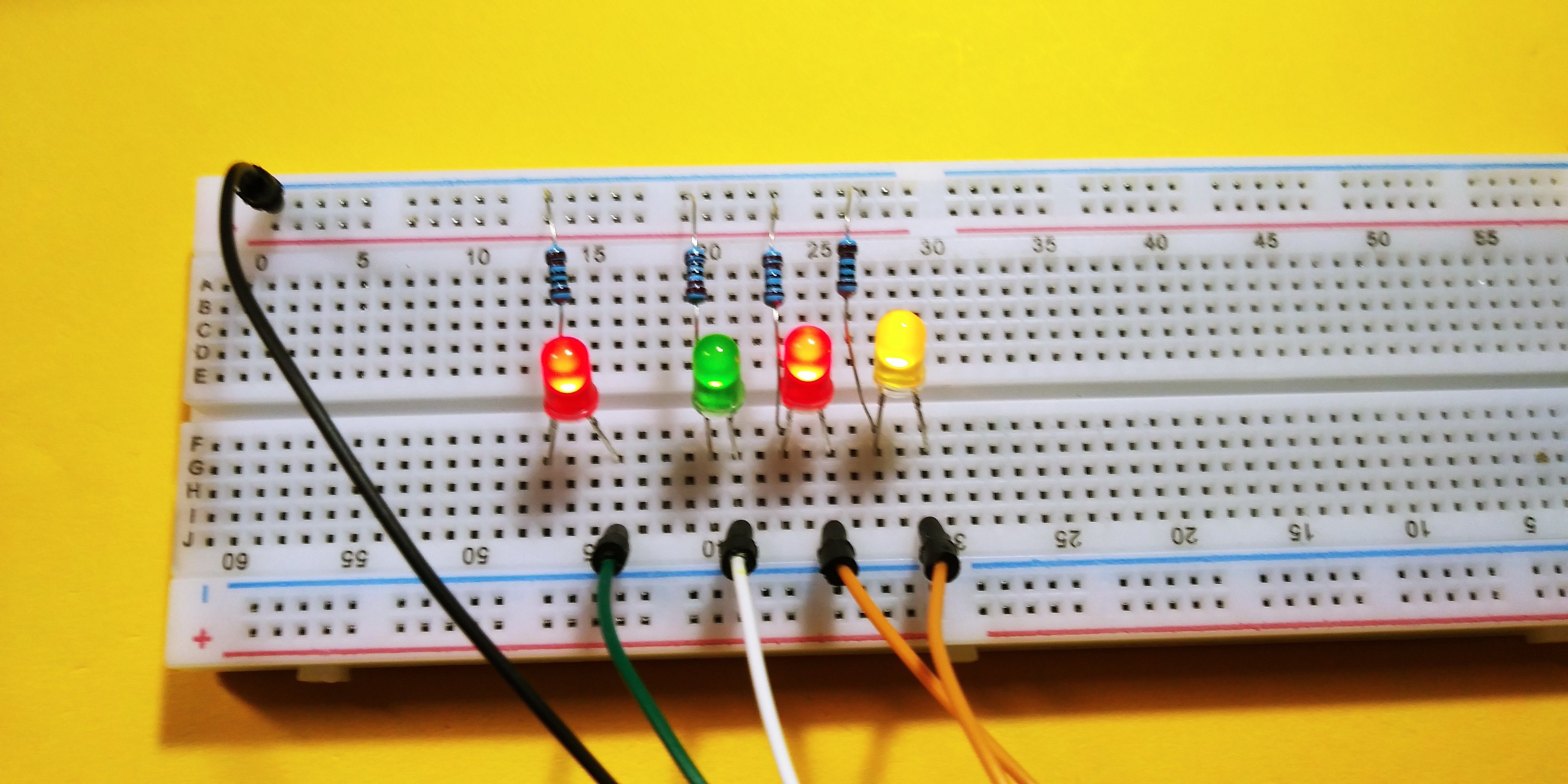
Now we’ll insert the resistors into the breadboard. Space the resistors out with one leg connected to the the negative rail.

Now its time to insert the LEDs. Before inserting the LEDs, its important to note that the longer of the two leads on most through-hole LEDs is the positive leads. Connecting it the wrong way, will cause this circuit to not work

Connect the negative lead of the LED to the horizontal rail on which the resistor is connected and connect the positive lead to an adjacent rail. Repeat this process for all 2 LEDs. Now its time to complete the circuit.

We are going to use output ports 13, 12 for the input signal. Connect the positive lead of the LED on the right to pin 13 and the LED on the left to pin 12. The circuit is now complete. Power on the Arduino Uno by connecting it to your computer using the USB cable. The LEDs on the board turn on and the board powers up.
SOFTWARE
Before we work on our sketch, make sure to download the Arduino IDE for your specific operating system. I’ll leave a link to where you can download this software:

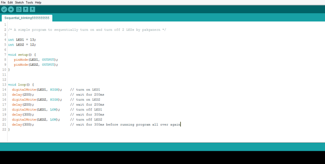
i make a sketch go ahead and copy this Sketch to run this program, using this code:
/* A simple program to sequentially turn on and turn off 2 LEDs by pakganern */
int LED1 = 13;int LED2 = 12;
void setup() { pinMode(LED1, OUTPUT); pinMode(LED2, OUTPUT);}void loop() { digitalWrite(LED1, HIGH); // turn on LED1 delay(200); // wait for 200ms digitalWrite(LED2, HIGH); // turn on LED2 delay(200); // wait for 200ms digitalWrite(LED1, LOW); // turn off LED1 delay(300); // wait for 300ms digitalWrite(LED2, LOW); // turn off LED2 delay(300); // wait for 300ms before running program all over again}VERIFY/COMPILE the upload it to the board.
once done your LEDs should atart blinking in sequence like this;

the first code creates 2 variables. LED1, LED2. This allows us to change the output pins, without having to modify the entire program. The code in the setup part of the program tells the arduino that pins 13 and 12 will be outputs. The loop portion of the program is where the actual instructions live. The first two digitalwrite functions turn on one LED at a time with a 200ms delay between each of them turning on. The next two digitalwrite functions turn off the leds with a 300ms delay between each LED. Now you can change the delay between each LED to change the rhythm of the LEDs turning on and off.
I make another sketch that i will share on this post you can use this if you want, in this code i set 4 leds in sequence. here is the code:
/* A simple program to sequentially turn on and turn off 2 LEDs by pakganern */
int LED1 = 12;int LED2 = 11;int LED3 = 10;int LED4 = 9;
void setup() { pinMode(LED1, OUTPUT); pinMode(LED2, OUTPUT); pinMode(LED3, OUTPUT); pinMode(LED4, OUTPUT);}void loop() { digitalWrite(LED1, HIGH); // turn on LED1 delay(200); digitalWrite(LED2, HIGH); // turn on LED2 delay(200); digitalWrite(LED3, HIGH); // turn on LED3 delay(200); digitalWrite(LED4, HIGH); // turn on LED4 delay(200); digitalWrite(LED1, LOW); // turn on LED1 delay(300); digitalWrite(LED2, LOW); // turn on LED2 delay(300); digitalWrite(LED3, LOW); // turn on LED3 delay(300); digitalWrite(LED4, LOW); // turn on LED4 delay(300); // wait for 300ms before running program all over again; }
Hope this tutorial was useful. Please hit upvote for more Arduino tutorials and follow me @pakganern
![20180105_182452[1].jpg](https://steemitimages.com/0x0//https://res.cloudinary.com/hpiynhbhq/image/upload/v1515220008/ws4hb3gvt9qhc2tw61pa.jpg)
Posted on Utopian.io - Rewarding Open Source Contributors
The best
Thank you for the contribution. It has been approved.
You can contact us on Discord.
[utopian-moderator]
Hey @pakganern I am @utopian-io. I have just upvoted you!
Achievements
Suggestions
Get Noticed!
Community-Driven Witness!
I am the first and only Steem Community-Driven Witness. Participate on Discord. Lets GROW TOGETHER!
Up-vote this comment to grow my power and help Open Source contributions like this one. Want to chat? Join me on Discord https://discord.gg/Pc8HG9x