How to use shift register in 8 LEDs in Arduino
Today i will going share how to use shift register on 8 leds in arduino, as you see it on the picture below.

In this post focuses on the 74HC595N shift register which is the little microchip shown below. so what is shift register? Let us suppose we are doing a project that needs to update three, 7-segment LEDs. Each 7-segment LED requires 7 pins from your Arduino. That means you’ll need 21 pins from your Arduino to drive all 3 LEDs, the problem is arduino don’t have 21 output pins to support the project, so how can we do this lets try a 8 LEDs using a shift register and lets find out.. to find more info about about shift register click this link

In this tutorial we need these couple of components:
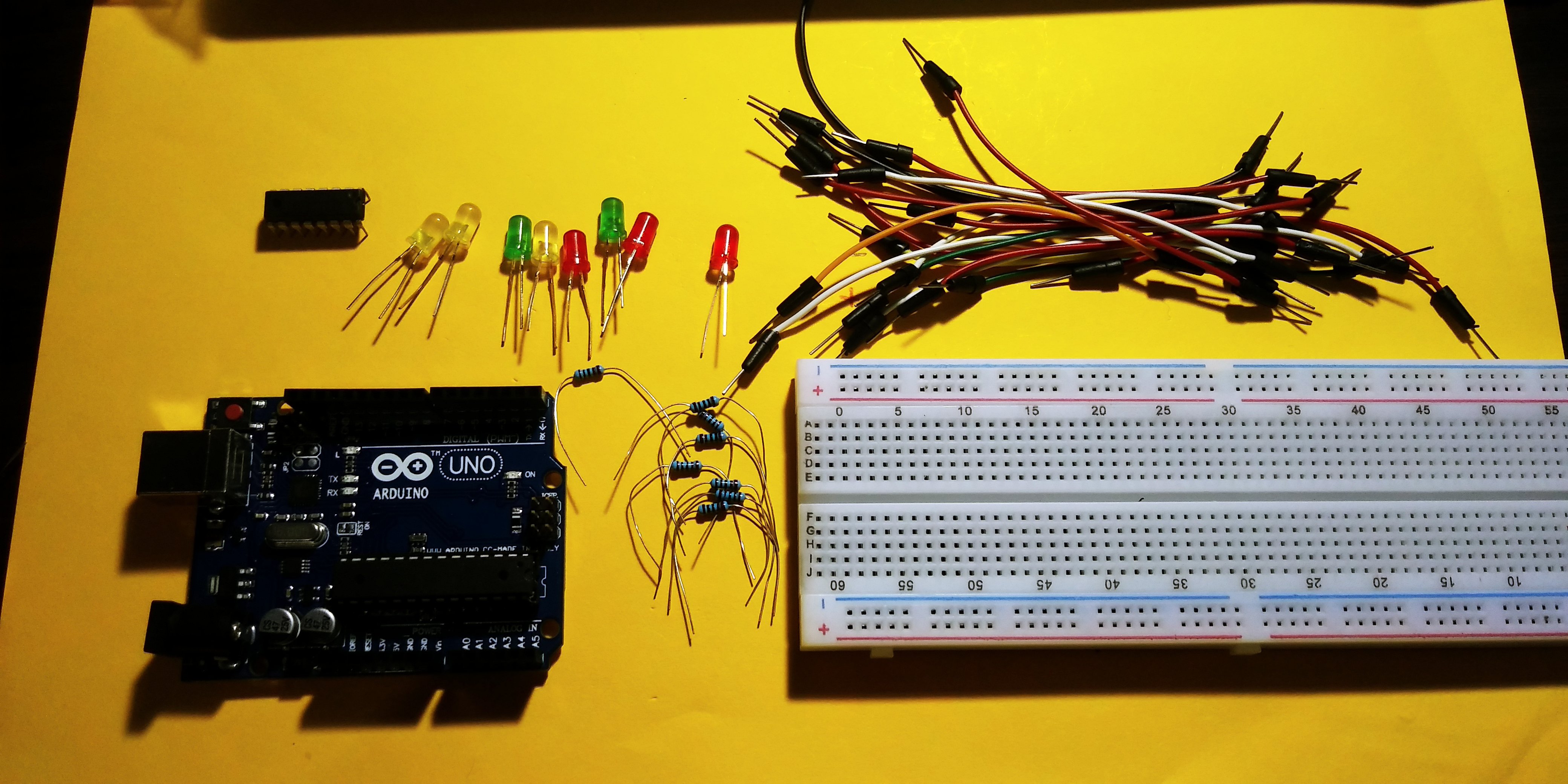
HARDWARE
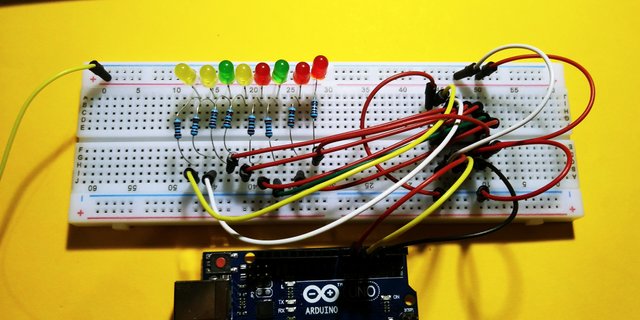
First i placed the shift register on the breadboard and the 8 LEDs the postive leg of the leds to the vertical rail and the negative to the horizontal rail of the board.

Place the resistors on the positive leg of the LEDs.

SHIFT REGISTER SCHEMATIC
A shift register has two 8-bit registers. The first register is called the “stage” register and is where the last byte is sitting that you wrote to it. The second 8-bit register is for storage and you tell the shift register microchip to transfer the “stage” shift register to the “storage” shift register. The “storage” register is mapped to the output PINs Q0 through Q7.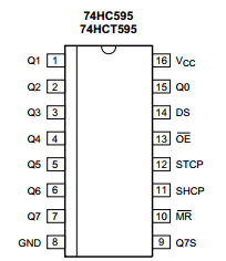
Lets start wiring with the left outputs first.

SOFTWARE
Before we work on our sketch, make sure to download the Arduino IDE for your specific operating system. I’ll leave a link to where you can download this software: https://www.arduino.cc/en/Main/Software

Arduino Sketch Using One Shift Register and 8 LEDs

copy the code here:
const int DATAPIN1 = 4; // DSconst int LATCHPIN1 = 5; // STCPconst int CLOCKPIN1 = 6; // SHCPint ledValue = 1;void setup() { pinMode(DATAPIN1, OUTPUT); pinMode(LATCHPIN1, OUTPUT); pinMode(CLOCKPIN1, OUTPUT); }void loop() { digitalWrite(LATCHPIN1, LOW);
shiftOut(DATAPIN1, CLOCKPIN1, MSBFIRST, ledValue); digitalWrite(LATCHPIN1, HIGH);
ledValue = ledValue * 2; if (ledValue > 128) { ledValue = 1; } delay(500);
the Shift registers provide a way to save output pins. They are pretty simple to use and cheap, the source of the code is came from GITHUB and here is the result of my work.

thank you for stopping by, if you like it please upvote and follow me @pakganern
![20180105_182452[1].jpg](https://steemitimages.com/0x0//https://res.cloudinary.com/hpiynhbhq/image/upload/v1515246317/p1ndpuqabrufndh27b7o.jpg)
Posted on Utopian.io - Rewarding Open Source Contributors
Thank you for the contribution. It has been approved.
You can contact us on Discord.
[utopian-moderator]
what a nice flashback of my university days. there's so much we can do with arduino indeed. our project back then was a mobot to follow a path. well it's really nice to have read this. cheers!
Hey @pakganern I am @utopian-io. I have just upvoted you!
Achievements
Suggestions
Get Noticed!
Community-Driven Witness!
I am the first and only Steem Community-Driven Witness. Participate on Discord. Lets GROW TOGETHER!
Up-vote this comment to grow my power and help Open Source contributions like this one. Want to chat? Join me on Discord https://discord.gg/Pc8HG9x