How to make 12 LED chaser without shift register
Today i will going to share a basic arduino experiment on how to make 12 led chaser in arduino un board, This is a LED Chaser, with the simplest code. we can have different LED glowing arrangements, like Knight Rider is kinda famous, you can make it by simply putting the same loop but with descending outputs try it. so what you can learn on this post is, you can actually make your own christmas lights:) you can make this like a school invention, and you can learn a simple programming in arduino.
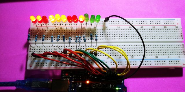
Requirements
The requirements for this activity is just a basic parts in arduino, what we have are:
This is just a BASIC tutorial anf you gonna have to do is follow the circuit diagram i made, connect the led to the right pin on the arduino, so lets the invention, you can use my fritzing below;
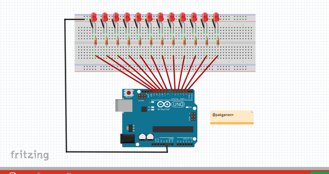
We don't need to use a shift register chip to 12 leds beacause the uno has 13 digital pins to make an output so lets start with the wiring, LED has 2 legs the long one is the common anode which means its a possitive and the short leg will be the cathode which is the GND or the negative leg. we need to use resistor to limit or we can say it regulates the amount of power that flows into the led, resistor is made from winding Nichrome or similar wire on an insulating form. This component, called a wirewound resistor and it can be able to handle higher currents. i started to put the led and the resistor into the breadboard.
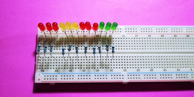
I use RED/YELLOW/GREEN leds and 12 220ohm resistance Arduino has two GND actually 3 GND pins 2 is along with power pins and other one is along with digital pins. Both of the GND pins are common, so you may connect the common cathode leg of the leds on the any GND pin. we have to put the short leg of the led to the horizzontal rail on the breadboard.
This like connecting an object in grade school so its easy with a diagram to follow, and here it is the circuit is complete so go forward to the software.
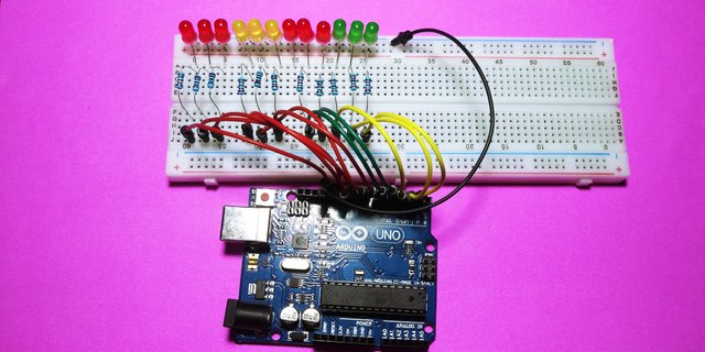
We are done building the circuit so lets start to set up and make a code for this. we are going to use the arduino ide, to set the sketch for this, if you dont have make sure to download the Arduino IDE for your specific operating system. I’ll leave a link to where you can download this software: https://www.arduino.cc/en/Main/Software

PIN 2 to 13 are the output pins to the leds, here the sketch for this chaser:
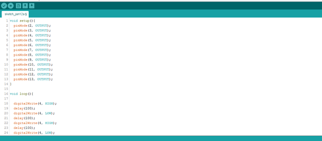
This is very SHORT code if you want to copy the code, you can copy it below:
void setup(){
  pinMode(2, OUTPUT);
  pinMode(3, OUTPUT);
  pinMode(4, OUTPUT);
  pinMode(5, OUTPUT);
  pinMode(6, OUTPUT);
  pinMode(7, OUTPUT);
  pinMode(8, OUTPUT);
  pinMode(9, OUTPUT);
  pinMode(10, OUTPUT);
  pinMode(11, OUTPUT);
  pinMode(12, OUTPUT);
  pinMode(13, OUTPUT);
}
void loop(){
  digitalWrite(4, HIGH);
  delay(100);
  digitalWrite(4, LOW);
  delay(100);
  digitalWrite(4, HIGH);
  delay(100);
  digitalWrite(4, LOW);
  delay(100);
  digitalWrite(8, HIGH);
  delay(100);
  digitalWrite(8, LOW);
  delay(100);
  digitalWrite(8, HIGH);
  delay(100);
  digitalWrite(8, LOW);
  delay(100);
  digitalWrite(2, HIGH);
  delay(100);
  digitalWrite(2, LOW);
  delay(100);
  digitalWrite(2, HIGH);
  delay(100);
  digitalWrite(2, LOW);
  delay(100);
  digitalWrite(10, HIGH);
  delay(100);
  digitalWrite(10, LOW);
  delay(100);
  digitalWrite(10, HIGH);
  delay(100);
  digitalWrite(10, LOW);
  delay(100);
  digitalWrite(3, HIGH);
  delay(100);
  digitalWrite(3, LOW);
  delay(100);
  digitalWrite(3, HIGH);
  delay(100);
  digitalWrite(3, LOW);
  delay(100);
  digitalWrite(13, HIGH);
  delay(100);
  digitalWrite(13, LOW);
  delay(100);
  digitalWrite(13, HIGH);
  delay(100);
  digitalWrite(13, LOW);
  delay(100);
  digitalWrite(7, HIGH);
  delay(100);
  digitalWrite(7, LOW);
  delay(100);
  digitalWrite(7, HIGH);
  delay(100);
  digitalWrite(7, LOW);
  delay(100);
  digitalWrite(12, HIGH);
  delay(100);
  digitalWrite(12, LOW);
  delay(100);
  digitalWrite(12, HIGH);
  delay(100);
  digitalWrite(12, LOW);
  delay(100);
  digitalWrite(5, HIGH);
  delay(100);
  digitalWrite(5, LOW);
  delay(100);
  digitalWrite(5, HIGH);
  delay(100);
  digitalWrite(5, LOW);
  delay(100);
  digitalWrite(11, HIGH);
  delay(100);
  digitalWrite(11, LOW);
  delay(100);
  digitalWrite(11, HIGH);
  delay(100);
  digitalWrite(11, LOW);
  delay(100);
  digitalWrite(6, HIGH);
  delay(100);
  digitalWrite(6, LOW);
  delay(100);
  digitalWrite(6, HIGH);
  delay(100);
  digitalWrite(6, LOW);
  delay(100);
  digitalWrite(9, HIGH);
  delay(100);
  digitalWrite(9, LOW);
  delay(100);
  digitalWrite(9, HIGH);
  delay(100);
  digitalWrite(9, LOW);
  delay(100);
  digitalWrite(13, HIGH);
  delay(100);
  digitalWrite(13, LOW);
  delay(100);
  digitalWrite(12, HIGH);
  delay(100);
  digitalWrite(12, LOW);
  delay(100);
  digitalWrite(11, HIGH);
  delay(100);
  digitalWrite(11, LOW);
  delay(100);
  digitalWrite(10, HIGH);
  delay(100);
  digitalWrite(10, LOW);
  delay(100);
  digitalWrite(9, HIGH);
  delay(100);
  digitalWrite(9, LOW);
  delay(100);
  digitalWrite(8, HIGH);
  delay(100);
  digitalWrite(8, LOW);
  delay(100);
  digitalWrite(7, HIGH);
  delay(100);
  digitalWrite(7, LOW);
  delay(100);
  digitalWrite(6, HIGH);
  delay(100);
  digitalWrite(6, LOW);
  delay(100);
  digitalWrite(5, HIGH);
  delay(100);
  digitalWrite(5, LOW);
  delay(100);
  digitalWrite(4, HIGH);
  delay(100);
  digitalWrite(4, LOW);
  delay(100);
  digitalWrite(3, HIGH);
  delay(100);
  digitalWrite(3, LOW);
  delay(100);
  digitalWrite(2, HIGH);
  delay(100);
  digitalWrite(2, LOW);
  delay(100);
  digitalWrite(2, HIGH);
  delay(100);
  digitalWrite(3, HIGH);
  delay(100);
  digitalWrite(4, HIGH);
  delay(100);
  digitalWrite(5, HIGH);
  delay(100);
  digitalWrite(6, HIGH);
  delay(100);
  digitalWrite(7, HIGH);
  delay(100);
  digitalWrite(8, HIGH);
  delay(100);
  digitalWrite(9, HIGH);
  delay(100);
  digitalWrite(10, HIGH);
  delay(100);
  digitalWrite(11, HIGH);
  delay(100);
  digitalWrite(12, HIGH);
  delay(100);
  digitalWrite(13, HIGH);
  delay(100);
  digitalWrite(2,LOW);
  delay(100);
  digitalWrite(3,LOW);
  delay(100);
  digitalWrite(4,LOW);
  delay(100);
  digitalWrite(5,LOW);
  delay(100);
  digitalWrite(6,LOW);
  delay(100);
  digitalWrite(7,LOW);
  delay(100);
  digitalWrite(8,LOW);
  delay(100);
  digitalWrite(9,LOW);
  delay(100);
  digitalWrite(10,LOW);
  delay(100);
  digitalWrite(11,LOW);
  delay(100);
  digitalWrite(12,LOW);
  delay(100);
  digitalWrite(13,LOW);
  delay(100);
  digitalWrite(13,HIGH);
  delay(100);
  digitalWrite(2,HIGH);
  delay(100);
  digitalWrite(12,HIGH);
  delay(100);
  digitalWrite(3,HIGH);
  delay(100);
  digitalWrite(11,HIGH);
  delay(100);
  digitalWrite(4,HIGH);
  delay(100);
  digitalWrite(10,HIGH);
  delay(100);
  digitalWrite(5,HIGH);
  delay(100);
  digitalWrite(9,HIGH);
  delay(100);
  digitalWrite(6,HIGH);
  delay(100);
  digitalWrite(8,HIGH);
  delay(100);
  digitalWrite(7,HIGH);
  delay(100);
  digitalWrite(2, HIGH);
  delay(100);
  digitalWrite(2, LOW);
  delay(100);
  digitalWrite(3, HIGH);
  delay(100);
  digitalWrite(3, LOW);
  delay(100);
  digitalWrite(4, HIGH);
  delay(100);
  digitalWrite(4, LOW);
  delay(100);
  digitalWrite(5, HIGH);
  delay(100);
  digitalWrite(5, LOW);
  delay(100);
  digitalWrite(6, HIGH);
  delay(100);
  digitalWrite(6, LOW);
  delay(100);
  digitalWrite(7, HIGH);
  delay(100);
  digitalWrite(7, LOW);
  delay(100);
  digitalWrite(8, HIGH);
  delay(100);
  digitalWrite(8, LOW);
  delay(100);
  digitalWrite(9, HIGH);
  delay(100);
  digitalWrite(9, LOW);
  delay(100);
  digitalWrite(10, HIGH);
  delay(100);
  digitalWrite(10, LOW);
  delay(100);
  digitalWrite(11, HIGH);
  delay(100);
  digitalWrite(11, LOW);
  delay(100);
  digitalWrite(12, HIGH);
  delay(100);
  digitalWrite(12, LOW);
  delay(100);
  digitalWrite(13, HIGH);
  delay(100);
  digitalWrite(13, LOW);
  delay(100);
  digitalWrite(2, HIGH);
  delay(100);
  digitalWrite(3, HIGH);
  delay(100);
  digitalWrite(4, HIGH);
  delay(100);
  digitalWrite(5, HIGH);
  delay(100);
  digitalWrite(6, HIGH);
  delay(100);
  digitalWrite(7, HIGH);
  delay(100);
  digitalWrite(8, HIGH);
  delay(100);
  digitalWrite(9, HIGH);
  delay(100);
  digitalWrite(10, HIGH);
  delay(100);
  digitalWrite(11, HIGH);
  delay(100);
  digitalWrite(12, HIGH);
  delay(100);
  digitalWrite(13, HIGH);
  delay(100);
  digitalWrite(13,LOW);
  delay(100);
  digitalWrite(12,LOW);
  delay(100);
  digitalWrite(11,LOW);
  delay(100);
  digitalWrite(10,LOW);
  delay(100);
  digitalWrite(9,LOW);
  delay(100);
  digitalWrite(8,LOW);
  delay(100);
  digitalWrite(7,LOW);
  delay(100);
  digitalWrite(6,LOW);
  delay(100);
  digitalWrite(5,LOW);
  delay(100);
  digitalWrite(4,LOW);
  delay(100);
  digitalWrite(3,LOW);
  delay(100);
  digitalWrite(2,LOW);
  delay(100);
  digitalWrite(2, HIGH);
  delay(100);
  digitalWrite(2, LOW);
  delay(100);
  digitalWrite(3, HIGH);
  delay(100);
  digitalWrite(3, LOW);
  delay(100);
  digitalWrite(4, HIGH);
  delay(100);
  digitalWrite(4, LOW);
  delay(100);
  digitalWrite(5, HIGH);
  delay(100);
  digitalWrite(5, LOW);
  delay(100);
  digitalWrite(6, HIGH);
  delay(100);
  digitalWrite(6, LOW);
  delay(100);
  digitalWrite(7, HIGH);
  delay(100);
  digitalWrite(7, LOW);
  delay(100);
  digitalWrite(8, HIGH);
  delay(100);
  digitalWrite(8, LOW);
  delay(100);
  digitalWrite(9, HIGH);
  delay(100);
  digitalWrite(9, LOW);
  delay(100);
  digitalWrite(10, HIGH);
  delay(100);
  digitalWrite(10, LOW);
  delay(100);
  digitalWrite(11, HIGH);
  delay(100);
  digitalWrite(11, LOW);
  delay(100);
  digitalWrite(12, HIGH);
  delay(100);
  digitalWrite(12, LOW);
  delay(100);
  digitalWrite(13, HIGH);
  delay(100);
  digitalWrite(13, LOW);
  delay(100);
  digitalWrite(13, HIGH);
  delay(100);
  digitalWrite(12, HIGH);
  delay(100);
  digitalWrite(11, HIGH);
  delay(100);
  digitalWrite(10, HIGH);
  delay(100);
  digitalWrite(9, HIGH);
  delay(100);
  digitalWrite(8, HIGH);
  delay(100);
  digitalWrite(7, HIGH);
  delay(100);
  digitalWrite(6, HIGH);
  delay(100);
  digitalWrite(5, HIGH);
  delay(100);
  digitalWrite(4, HIGH);
  delay(100);
  digitalWrite(3, HIGH);
  delay(100);
  digitalWrite(2, HIGH);
  delay(100);
  digitalWrite(13,LOW);
  delay(100);
  digitalWrite(2,LOW);
  delay(100);
  digitalWrite(12,LOW);
  delay(100);
  digitalWrite(3,LOW);
  delay(100);
  digitalWrite(11,LOW);
  delay(100);
  digitalWrite(4,LOW);
  delay(100);
  digitalWrite(10,LOW);
  delay(100);
  digitalWrite(5,LOW);
  delay(100);
  digitalWrite(9,LOW);
  delay(100);
  digitalWrite(6,LOW);
  delay(100);
  digitalWrite(8,LOW);
  delay(100);
  digitalWrite(7,LOW);
  delay(100);
  digitalWrite(13, HIGH);
  delay(100);
  digitalWrite(12, HIGH);
  delay(100);
  digitalWrite(11, HIGH);
  delay(100);
  digitalWrite(11,LOW);
  delay(100);
  digitalWrite(12,LOW);
  delay(100);
  digitalWrite(13,LOW);
  delay(100);
}
You can change the delay time of the led on the sketch, so lets upload it to the board and lets see how its works,

You see it, its a christmas lights with a code, i hope you enjoy this actitvity if wan to learn how arduino works, and how to make a sketch, then maybe this blog might help you, i was inspired by engmousaalkaabi for this wonderful stuff. so thats it, if you want to know and see my future activity follow me! thank you.
You can also check my previous posts:
Control LED using Push Buttons/ Visual programming using XOD
Control Servo motor using Joystick
Stepper motor + Driver Uln2003 in arduino
Control Servo motor using potentiometer - arduino
![20180105_182452[1].jpg](https://steemitimages.com/640x0/https://res.cloudinary.com/hpiynhbhq/image/upload/v1515769039/um1okjtupm9o5okqpd3f.jpg)
Posted on Utopian.io - Rewarding Open Source Contributors
Thank you for the contribution. It has been approved.
You can contact us on Discord.
[utopian-moderator]
Hey @pakganern I am @utopian-io. I have just upvoted you!
Achievements
Suggestions
Get Noticed!
Community-Driven Witness!
I am the first and only Steem Community-Driven Witness. Participate on Discord. Lets GROW TOGETHER!
Up-vote this comment to grow my power and help Open Source contributions like this one. Want to chat? Join me on Discord https://discord.gg/Pc8HG9x
Oh my god, my wife asked me to buy a LED driver for the country house, but I don't want to do it myself. Can anyone advise where to buy it and how much it should cost?
Lmao, I understand I have no desire to assemble all the necessary equipment myself either. The prices of LED drivers depend on the power you need. In your case, it depends on the number and length of the lights. I have an ecopac led driver at home, it cost about £50. It's worth the money because it protects against overheating and short circuits, for my anxiety about the house is essential. I bought it for myself and for 3 years I have peace of mind that everything should be ok with my appliances. I think it's great. I'm thinking of buying a LED driver for the backyard now. We have a lot of lights hanging there too.