How to connect nokia 5110 LCD to arduino
Today in this instructable i will going to share on how to connect the nokia 5110 LCDto arduino use the code and use some web-based zip files and downloaded tools to create some awesome graphics you can customize however you want.

What you will learn in this tutorial s basically its on the title how to connect the 5110 LCD to arduino and how to add zip file library to arduino IDE, enough of me speaking, let's just begin.
Requirements

CIRCUIT DIAGRAM

Difficulty
When its come to difficulties this tutorial is just a basic one, all you have to do is to follow the circuit diagram and download the zip file library, just follow steps below.
Tutorial Contents
First let's connect the Nokia 5110 display. Remember that the LCD runs on 3.3V pin on the uno board and some people have connected it to 5V, it has worked but gave some weird grahics effects, so I suggest connecting to the 3.3V output of the arduino.

Lets connect the first 5 pin of the nokia 5110 LCD on the arduino board. which is pin 12 to pin 8 on digital pin.

The 3 pins remaining will be the VCC goes to pin 3.3v on the board the GND to GND and the light to GND. if we were going to connect a external power source the light should turn on, so lets work a code for it.

SOFTWARE
We are done building the circuit so lets start to set up and make a code for this. we are going to use the arduino ide, to set the sketch for this, if you dont have make sure to download the Arduino IDE for your specific operating system. I’ll leave a link to where you can download this software: https://www.arduino.cc/en/Main/Software

To get the code we need to download the zip file library from rinkydinkelectronics you can download it directly here http://www.rinkydinkelectronics.com/library.php?id=47

when the download is finished open the zip file then copy the folder name LCD5110_Graph on your desktop you can rename it as well.

Cut the folder in your desktop then go to your folders then locate the arduino folder>> libraries then paste it there. and now the folder LCD5110_Graph is already in the arduino ide libraries.

we have another option to add library on the arduino ide just use the ide to add the zip file, just click on the botton sketch>> include libraries>> then click add zip libraries<<

Locate the downlods folder where the LCD5110_Graph is downloaded then click on the zip file then wait until its added to the libraries

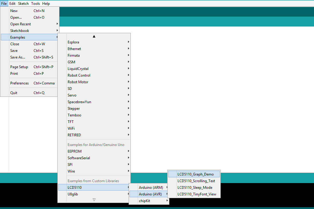
So now Let us work on the code now, on the arduino ide click the FILE tab>>examples>>then locate the for the LCD5110_Graph library . then click arduino AVR>>> then GRAPH_DEMO<<<
Upload the sketch code on your arduino board, base on the code we need to edit the pin lineage of 11,12 to12 first before 11 you can see on the code on the picture.

Copy the source code here:
// This program requires a Nokia 5110 LCD module.
//
// It is assumed that the LCD module is connected to
// the following pins using a levelshifter to get the
// correct voltage to the module.
//      SCK  - Pin 8
//      MOSI - Pin 9
//      DC   - Pin 10
//      RST  - Pin 11
//      CS   - Pin 12
//
#include <LCD5110_Graph.h
LCD5110 myGLCD(8,9,10,12,11);
extern uint8_t SmallFont[];
extern uint8_t arduino_logo[];
extern unsigned char TinyFont[];
extern uint8_t The_End[];
extern uint8_t pacman1[];
extern uint8_t pacman2[];
extern uint8_t pacman3[];
extern uint8_t pill[];
float y;
uint8_t* bm;
int pacy;
void setup()
{
  myGLCD.InitLCD();
  myGLCD.setFont(SmallFont);
  randomSeed(analogRead(7));
}
void loop()
{
  myGLCD.clrScr();
  myGLCD.drawBitmap(0, 0, arduino_logo, 84, 48);
  myGLCD.update();
  delay(2000);
  myGLCD.clrScr();
  myGLCD.print("LCD5110_Graph", CENTER, 0);
  myGLCD.print("DEMO", CENTER, 20);
  myGLCD.drawRect(28, 18, 56, 28);
  for (int i=0; i<6; i++)
  {
    myGLCD.drawLine(57, 18+(i*2), 83-(i*3), 18+(i*2));
    myGLCD.drawLine((i*3), 28-(i*2), 28, 28-(i*2));
  }
  myGLCD.setFont(TinyFont);
  myGLCD.print("(C)2015 by", CENTER, 36);
  myGLCD.print("Henning Karlsen", CENTER, 42);
  myGLCD.update();
  delay(5000);
  myGLCD.clrScr();
  for (int i=0; i<48; i+=2)
  {
    myGLCD.drawLine(0, i, 83, 47-i);
    myGLCD.update();
  }
  for (int i=83; i>=0; i-=2)
  {
    myGLCD.drawLine(i, 0, 83-i, 47);
    myGLCD.update();
  }
  delay(2000);
  myGLCD.clrScr();
  myGLCD.drawRect(0, 0, 83, 47);
  for (int i=0; i<48; i+=4)
  {
    myGLCD.drawLine(0, i, i*1.75, 47);
    myGLCD.update();
  }
  for (int i=0; i<48; i+=4)
  {
    myGLCD.drawLine(83, 47-i, 83-(i*1.75), 0);
    myGLCD.update();
  }
  delay(2000);
  myGLCD.clrScr();
  for (int i=0; i<8; i++)
  {
    myGLCD.drawRoundRect(i*3, i*3, 83-(i*3), 47-(i*3));
    myGLCD.update();
  }
  delay(2000);
  myGLCD.clrScr();
  for (int i=0; i<17; i++)
  {
    myGLCD.drawCircle(41, 23, i*3);
    myGLCD.update();
  }
  delay(2000);
  myGLCD.clrScr();
  myGLCD.drawRect(0, 0, 83, 47);
  myGLCD.drawLine(0, 23, 84, 23);
  myGLCD.drawLine(41, 0, 41, 47);
  for (int c=0; c<4; c++)
  {
    for (int i=0; i<84; i++)
    {
      y=i*0.017453292519943295769236907684886;
      myGLCD.invPixel(i, (sin(y*6)*20)+23);
      myGLCD.update();
      delay(20);
    }
  }
  delay(2000);
  for (int pc=0; pc<3; pc++)
  {
    pacy=random(0, 28);
    for (int i=-20; i<84; i++)
    {
      myGLCD.clrScr();
      for (int p=4; p>((i+20)/20); p--)
        myGLCD.drawBitmap(p*20-8, pacy+7, pill, 5, 5);
      switch(((i+20)/3) % 4)
      {
        case 0: bm=pacman1;
                break;
        case 1: bm=pacman2;
                break;
        case 2: bm=pacman3;
                break;
        case 3: bm=pacman2;
                break;
      }
      myGLCD.drawBitmap(i, pacy, bm, 20, 20);
      myGLCD.update();
      delay(25);
    }
  }
  for (int i=0; i<25; i++)
  {
    myGLCD.clrScr();
    myGLCD.drawBitmap(0, i-24, The_End, 84, 24);
    myGLCD.update();
    delay(100);
  }
  myGLCD.setFont(SmallFont);
  myGLCD.print("Runtime (ms):", CENTER, 32);
  myGLCD.printNumI(millis(), CENTER, 40);
  myGLCD.update();
  for (int i=0; i<5; i++)
  {
    myGLCD.invert(true);
    delay(1000);
    myGLCD.invert(false);
    delay(1000);
  }
}
lets upload it to the board and lets see how its works;
![20180116_203458[1].gif](https://steemitimages.com/0x0//https://res.cloudinary.com/hpiynhbhq/image/upload/v1516116775/nctdcsbjw01dazplqtfz.gif)
This is my first project using the nokia 5110 LCD so i hope you enjoy this actitvity if want to learn how arduino works, and how to make a sketch, then maybe this blog might help you, i was inspired by educ8 for this wonderful stuff. so thats it, if you want to know and see my future activity follow me! and dont forget to follow me! thank you.
You can also check my previous posts:
TM1637 4 digit 7-segment display with Arduino How to adjust LED brightness using potentiometer/ visual programming XOD How to make 12 LED chaser without shift Control LED using Push Buttons/ Visual programming using XOD Control Servo motor using Joystick Stepper motor + Driver Uln2003 in arduino Control Servo motor using potentiometer - arduino
Posted on Utopian.io - Rewarding Open Source Contributors
Thanks for sharing we understood your poat
thanks
Thank you for the contribution. It has been approved.
You can contact us on Discord.
[utopian-moderator]
Hey @pakganern I am @utopian-io. I have just upvoted you!
Achievements
Suggestions
Get Noticed!
Community-Driven Witness!
I am the first and only Steem Community-Driven Witness. Participate on Discord. Lets GROW TOGETHER!
Up-vote this comment to grow my power and help Open Source contributions like this one. Want to chat? Join me on Discord https://discord.gg/Pc8HG9x