How to design and simulate a full wave precision rectifier using Qucs.
Photocredit
for this activity you must remember the concepts shown below.
Operational Amplifier.
Currently, the term operational amplifier refers to an integrated circuit that is used in a wide variety of different applications. The operational amplifiers are characterized by their differential input and very high gain. In general, the amplifier is powered by both positive and negative sources, which allows for excursions both above and below ground (or the reference point to be considered).
full wave precision rectifier.
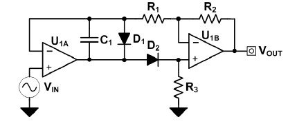
The precision rectifier transmits one polarity of the signal and inverts the other (the negative side). The full wave precision rectifier uses both halves of the sine wave input; to obtain a unipolar output,
Activity
we will create a full wave precision rectifier and then we will see how to simulate the circuit using Qucs.
Photocredit
Circuit operation is shown in the picture below:

Photocredit
Requirements
- laptop with Qucs software installed.
Difficulty
This tutorial is for those who know the basics of Electronic circuits.
Steps to follow
now let's step by step create this full wave rectifier to finally simulate it.
- Prepare the equipment needed for the activity.
- Open the Qucs software.
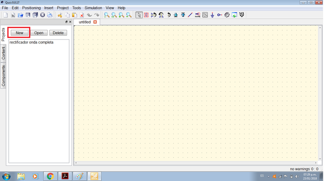
- Open a new project and let's get to work.
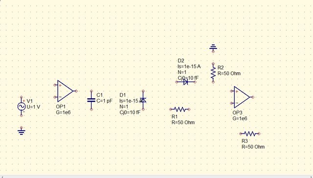
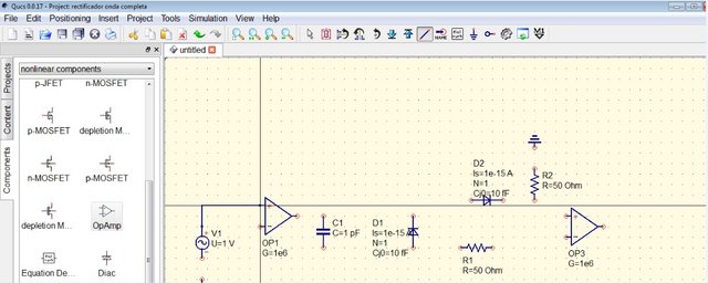
first we need to add all the circuits components:
- 1 Input Signal (AC - 1V - 500Hz)
- 1KOhm resistor (x3)
- 2 OpAmp
- 47pF Capacitor
- 2 Diodes
- 2 Ground
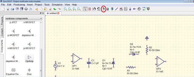
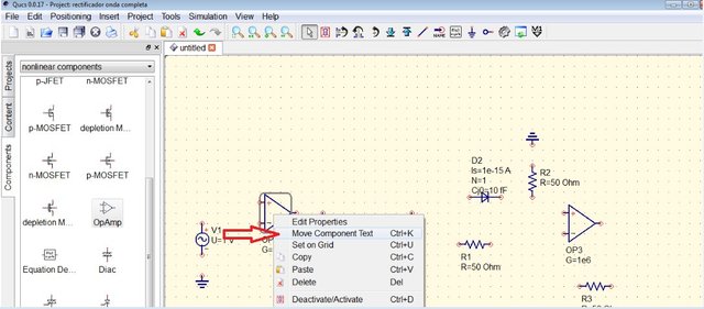
Right click the circuit components to move anywhere in the simulation area.
Click on the rotation tool to position components in any orientation.
Click wire to start connecting the circuit.
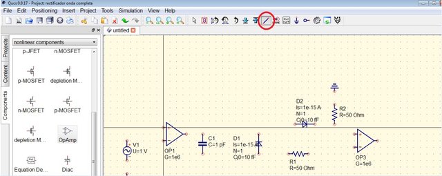
Then click the desired pins to be connected.
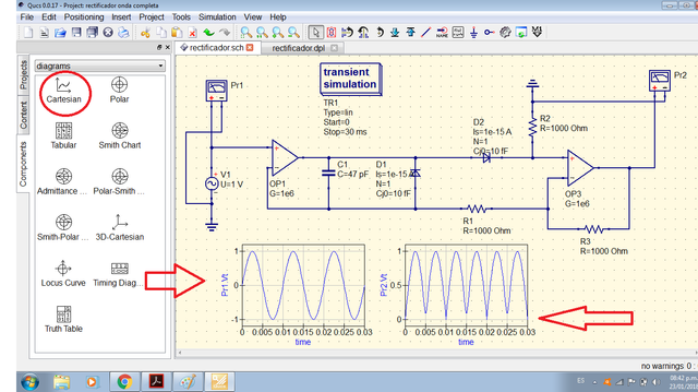
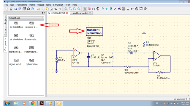
After making all the connections we place the transient simulation as shown in the following image:
In order to see the input and output signal we put a voltage probe in each one of them, then we started the simulation.
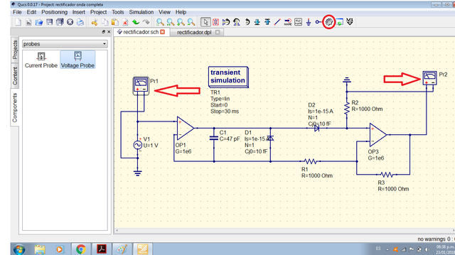
we add 2 Cartesian diagrams, in one diagram we graph the input signal and in another we graph the rectified signal.
try it and start learning.
Curriculum
These are my previous contributions:
Contributions
Posted on Utopian.io - Rewarding Open Source Contributors
Your contribution cannot be approved because it is not as informative as other contributions. See the Utopian Rules. Contributions need to be informative and descriptive in order to help readers and developers understand them.
You can contact us on Discord.
[utopian-moderator]
Upvote is the only thing I can support you.