[3d Modeling] Rebuilding the SteemPi Side Panel, a Fusion 360 Walk-Through
The Pitch
SteemPi is a Tv-Box Software that connects with the Steem blockchain and brings Steem related content, entertainment and much more to your TV or (spare) monitor. The SteemPi Software runs on inexpensive single board computers such as the Raspberry Pi.
[...]
Some time ago I designed a custom side panel for this case but until today i didn't made it available for others to download, and from the start of this 3d printed side panel project, i thought about sharing the model and what others could design and can come up with.
This is an interesting project.
Someone came to me in one of the Steemit Discord channels that I frequent and noticed that I tend to write about 3D printing on occasion, possibly more than I should. @Techtek was very gracious and let me know that he was putting out a project to embed a Raspberry Pi as a steem-specific streaming tool.
I've never been one to shy from a challenge nor am I one to see something that looks like fun and not get involved. Besides, it would give me the opportunity to do another step-by-step 3D modeling tutorial, and for some reason those things are really fun.
Let's get on that.
The Problem
There's a bit of a stumbling block to begin with. The provided model to start with is an STL file.
Those of you who are familiar with modifying STL know that a volumetric description based on the intersection of myriad triangles is a real bear when it comes to anything with curves. And look at this thing – the edges are all curves. Inevitably we are going to lose precision and detail if we start trying to poke at any of that structure.

There's only one thing we can do:
Use the STL as a guide and remodel the whole thing parametrically. As a result, we will at least end up with an STEP or IGES file which will accurately, losslessly, describe the object so that other people who prefer to work parametrically can start from something a little less rough.
Turn-by-Turn Into Geometry
Set up the file for import.
I'm going to assume that you are familiar with the very, very basics of Fusion 360 and don't need me to tell you how to start up the application, create new files, and so on. If you do – there are a multitude of really good tutorials available online and I encourage you to go and check them out as soon as possible.
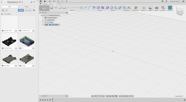
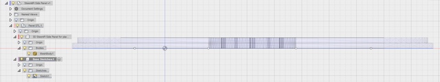
Here you'll see that I already have some design stuff for the Raspberry Pi and a folder set aside putting those designs so that I can find them later.
As always when you start a new project, you want to go in, create a New Component (which I have named Panel STL in this case) and then immediately save the file something notable so that you have something to work from.
Do not skip this step. Your life will be made vastly easier when you realize that having a component to work within and a file that is saved from the beginning gives you a place that you can fall back from and to on a regular basis. In the case of a crash at the worst possible time, this can save your entire project.
Great. Now that we have created a place to work, let's get that side panel out of the way and get the STL on screen.
Get that sucker imported.
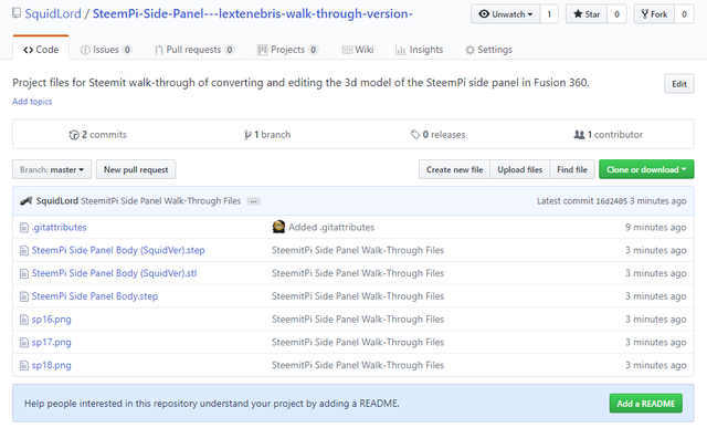
Here's a warning: the link that says STL on the original blog entry? That's not a link to an STL file directly. You're going to have to click on that link, end up on the GitHub server, see the model, and from there click the download button.
If you don't follow that process explicitly, you'll end up with a file which is pointedly not an STL file and which can't be pulled into any modeling system.
(I'm not saying that this happened to me – but learn from my cautionary tale.
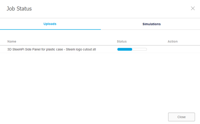
Now that you have properly downloaded the STL source, all you need to do is choose the Upload button in the sidebar, select the file in question, and away it goes. Once it's up you'll see it over there along with the new file that you created to work on.
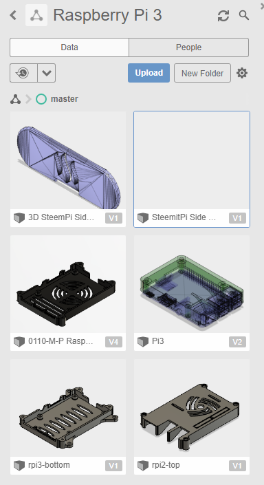
Your new file is empty so it has no thumbnail, of course, and the uploaded model is displayed as a triangular wireframe, all going according to plan. Everything looks good so far.
Grab the wireframe and drag it over into your current, open working window. Once you do that you can close the sidebar as we won't need to fiddle with that anymore at the moment.
We are almost there.
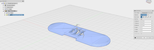
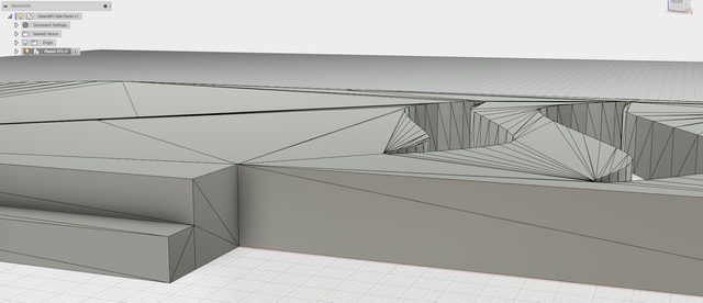
Look at the way that the object has imported. Does it look right?
It appears to be properly flat-side down. The larger face is facing the floor at the origin, which seems pretty good. The geometry is a little bit rough and a little bit low poly, but that's not going to matter much to us as we are going to just take the outlines as guidance measurement. The pattern in the middle we don't really care about because that's going to be the first thing to go…
This looks like something that we can clean up and make work.
Congratulations!
Confirm the placement and rotation and we're ready to go.
Cheat with both hands and convert to a BREP(?)
You will be terribly tempted at this point to go online, search around, and find a really good process for converting a mesh to a volumetric representation in Fusion 360 referred to as a BRep body. This generally involves turning off capturing activity in the file, then straightforwardly converting the mesh into a BRep, and Bob's your uncle, right?
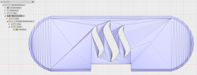
I've just done this for you. Look really closely at the representation above. Yes, it is a BRep body – but it has actual faces which make up the surface. Much of it is been smoothed, but there is a very tight section where triangles were very subdivided right along the middle of that section where you can tell there is some physical discontinuity.
This is a very tempting method.
It's also completely wrong.
Let's step back to before that happened and attack this the right way.
Build a basic sketch.
Everything has been reset back to where we started.
I've got a little further and right clicked on the subcomponent called "3D SteemPi side panel" and selected "Break Link" because they can get a little annoying when things update or fail to update because it's connected to an unchangeable source file. With the link broken, any changes that we make are limited to only affecting this particular file, which is exactly what we want.
Consider what we're looking at before we start doing anything. This is an orthographic top down view so no perspective is involved. We are looking at pure shapes.
The whole thing looks like the outline could be approximated with two circles connected at tangential points at the top and bottom, as well as a rectangular cut out at the bottom.
Let's take a look from the side.

This is an orthogonal view straight on from the front, and it reinforces what we saw from the top. We know that there are two layers, one of which is inset a little bit from the bottom and that rectangular cut out doesn't have any weird little edges, chamfers, or fillets. It's all a very straightforward, simple design.
That's going to make our next steps considerably easier.
Click on the navigation cube to flip the view back to the top, looking straight down.
This is where the actual work of remodeling this thing as smooth, complete structures really happens. And it's not nearly as hard as it might look at first glance.
Important safety tip: When you're drawing sketch entities, the pointer will snap to points and edges on other objects that already exist on another body, even if that other bodies in another component. This is going to help you a lot because we can use the geometry of that mesh to guide where we put points to build our sketch.
First thing, create new sketch. When it asks you what plane you want to draw that sketch on, select the bottom origin plane. That's the plane that the object is sitting on and exactly what we need.
I found that the easiest place to start the sketch is laying in the horizontal lines at the top and bottom on the outside. Zoom in closely at the upper left-hand "corner" where the curve meets the flat area. Feel around with your pointer with the line drawing tools selected and find that bit of geometry where it shifts. Left click, move over to the right where that flat bit stops and the curve starts again, feel around for the right spot, click and then select the checkmark to finish that line.
Do the same thing at the very bottom.
Now you have a couple of parallel lines which are attached to actual geometry.
The end curves are most easily done by choosing to draw three point arc, pick that top left point at the end of the line you just created, pick the bottom left point at the end of the line you just created, and then for the third point zoom in on the far outside edge on the left where that curve on the original object starts going vertical, feel around for a good point to attach it to, then left click.
Do the same thing on the right.
Now you've got the basic outside edge.
We know from looking at the side profile that there is a lip at the bottom and an inset bit at the top, and we can see where the color changes between those two parts of the original mesh. We could try and do the same thing that we already did but smaller, but that risks messing up some of the alignment or connecting to the wrong geometry – it's just tedious and we don't have to.
Choose the "Offset" tool. This thing will save you tons of time when you're doing sketches. Pick the outside perimeter that we just sketched and feel around with the slider that appears. You'll notice that the offset goes all the way around and you can kind of tell that the inner edge is about 10 mm from the outer edge according to this geometry, and because that's a pleasing and sensible number, it's probably right. Put 10 mm into the offset amount, hit enter, and you have that inner edge.
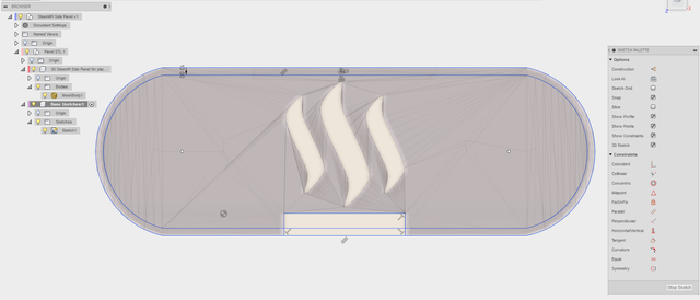
Now all we need is the rectangular cut out at the bottom, and that's easy.
You already know how to pick the line tool and feel around for the appropriate corners on geometry to select, so draw a line along that upper portion of the cut out which is anchored at either in the to the geometry. Once that's in place, dropping the vertical lines is really easy.
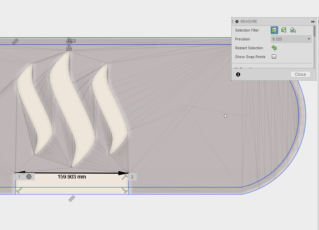
(The particularly astute among you have noticed that no part of this sketch is actually made reference to dimensions other than the offset. All of the lines are blue, indicating that they could potentially be dragged around. That's absolutely true. If you're particularly paranoid like me then you can use the Inspect tool to check some measurements of lines and of the distance between vertices. For instance, when I check the distance between the corners of the cut out, I get 159.903 mm. I would bet that the original design has a 160 mm opening there and this is probably within margin of error. If on a test printing this turned out to be too large or too small, it could be scaled or adjusted to better fit. For our purposes, right now, this looks pretty good.)
If you want to be a sketch completist, and I often am, you can go ahead and split the long line in the middle of the cut out and turn it into construction geometry or just trim the lines out entirely. This isn't required but it is nice.
Prepare the extrusions.
The universe is not made of flat surfaces, and so it becomes our job to thicken the world up a bit. Traces the outside of the form but without some volume is going to be completely useless.
Looking at it from the front again, it's obvious that there are only two surfaces that are worth defining. This is far too easy.
(Don't worry, we're going to make it harder for ourselves very soon.)
Just as before, we can easily extrude the sketch upwards to the appropriate thickness – but what's that appropriate thickness? We can just extrude and eyeball, as we did with the offset, and that would probably do well enough, or we can use the measure tool to determine the distance between two of the points on the end for each layer.
I'm going to cheat here and do just that even though it's less fun.
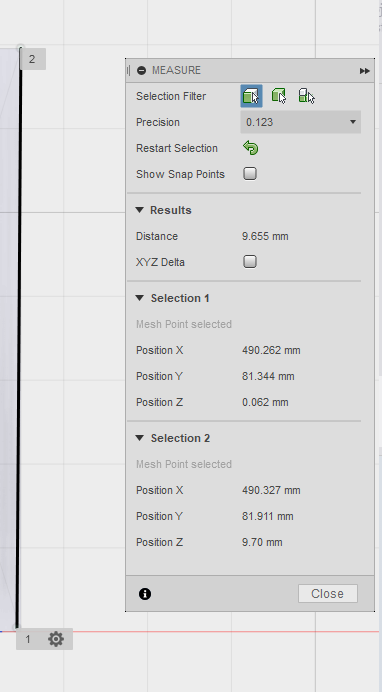
It looks like 10 mm is a good, solid estimation of what the thickness should probably be for each of these layers, which makes sense – industrial designers do try to keep the same proportions on a lot of the same structures which helps regularize how things appear.
Extrude the sketches.
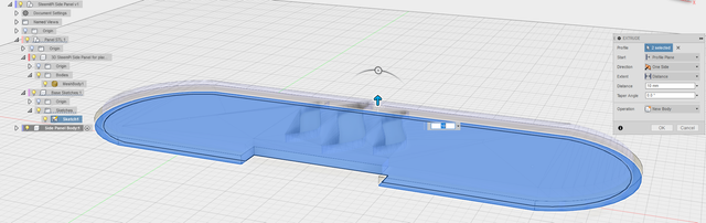
I've rotated our view a little bit so that we can have a little bit better feel for what we're doing. This is something that you will get comfortable with eventually but it can be a little hard to get a grasp on until you have some practice.
I've created yet another new component and named it "Side Panel Body" because you can never have too much organization. It also keeps me from screwing up parts of the model that I have already created and would like to stay right where they are. This is also hugely important.
Having selected the Push/Pull Tool, I select the two profiles from the sketch in the other component with a couple of simple left clicks. Drag it up a little bit and you'll have the control open up where you can just go ahead and put in 10 mm.
When you do this, the sketch that you are working from will have its little lightbulb in front turned off and it will become invisible. This is easy to deal with, just turn on the lightbulb in front of the sketch again in the browser on the left. Don't be surprised. Don't be shocked. Everything is normal.
Once the sketch is reengaged, Push/Pull again, select the interior profile alone, and pull it up to 20 mm. Sure, you could have it start at the top plane of the extrusion that we just made and extrude only 10 mm, and that would probably be a better solution for the parametric modelers in the audience – but I think we can handle this. No big deal.
Save and export your new, clean geometry.
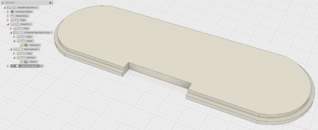
Now we have a very usable blank piece of geometry with quite specific design based off of the original mesh. It's perfectly flat, the curves are nicely managed, the cut out is appropriate to the size of the original mesh, and now we have a canvas set for making whatever modifications we want. All parametrically and all will adjust if the underlying sketches are adjusted.
It's now that I dig deep, export the model body as an STEP file, and slap that up somewhere. Anyone in the world can then pull that file down, put it into their choice of parametric CAD modeler and have clean geometry to start from.
We are now most of the way toward finishing this design. Which is pretty cool.
Arting It Up
Here is where things get either a little strange or little awesome, depending on where you stand on the issue of creating art. There are certain requirements for this particular piece as specified in the original pitch post. One of those requirements is that it have some slots for revealing some LEDs.
There need to be at least one hole where the 3 notification leds can shine through (Green(upvote), Blue(Comment), Purple(Not assigned yet)
Since we don't actually have any specifications for what kind of LEDs or LED mounts that are intended from the original design, and since this plate goes on the end of the Raspberry Pi where one of the major I/O connectors would go, thus the cut out block, and because this and is going to need some fairly significant ventilation as in the original cases, we're going to not actually design in any particular LED mounts but we are going to leave some artistic openings for both ventilation and potential future lighting options.
You could do this in a lot of ways, from your favorite vector drawing program which exports SVG or DXF, or even taking a new STL export and taking it into something like Mudbox to actually do sculpting on.
In this case, I'm going to take a relatively easy way out and create a new sketch, relatively free hand within the limits of parametric modeling, and use that to modify the part.
Let me get that basic sketch going.
Draw a new sketch.
Let's go for something relatively simple, just an offset curve which is reminiscent of the STEEM logo.
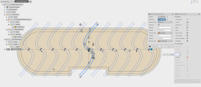
I started with a straightforward creation of a couple of crossed construction lines anchored to the middle point of both the top and the bottom, dividing it in half left to right. Then, rather than dividing the whole piece in half, I decided to simply divide the upper bit in half and retain the lower for a little bit of asymmetrical flavor.
Knowing that this thing is going to need to be constructed and that it will absolutely need some space at the edge to support the vertical bars that will eventually be the end plate, I dropped another offset line which took the edge of the plate and shifted it another 10 mm in. All of the things that we are going to do are going to only affect the part of the plate inside that border. There should be enough meat there to allow us to carve out pretty aggressively within.
The secret sauce is using the rectangular sketch pattern to reproduce the offset lines to either side, meaning that our only have to draw the central sketch once and let it be repeated by the system across the face. You'll notice that we can set the number of curves/shapes, the distance over which they extend, and in theory could shift them both up and down in the process.
Let's stick with this for sheer simplicity's sake and do another extrusion.
Cut right through the piece.
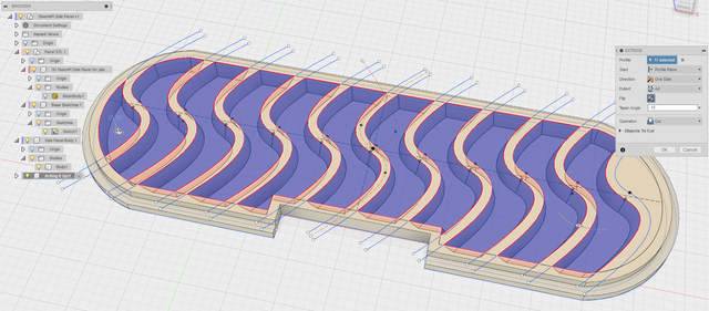
Extrusion does not only build up material, you can also use it to cut away.
Here I've effectively just selected the areas between the curves to be carved out and made use of the taper angle set to -15° in order to give it a little more depth and dimensionality. I have yet to select the last part of the sketch at the far right end, but when I do that will also appear to be cut out.
At this point this is almost a completed piece. I could apply some chamfers for a little more faceted visual effect or lay in some more sketch objects in order to create a more complicated open grill, but this should suffice to achieve all of the aims which we set out to do.
Chamfer, fillet, and prep for rendering.
Okay, maybe I couldn't resist adding just a little bit of a chamfer around the top and bottom inner edge and just a little bit of a curve fillet around to the outside of the inset so that when it is placed in the body there'll be just a little bit of shadow to outline the panel in place.
I just couldn't resist a little bit of razzle-dazzle.
I also used the material surface selector in Fusion 360 to give it a little metallic sheen so that things would stand out a little more clearly and look a bit more like what we expect. A nice black textured plastic would be more realistic, but we'll save that for rendering. In this environment using that texture would lose the lines.
But while we're here, let's take a look at what it would look like in the rendering environment with a nice, black textured plastic.
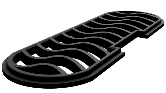
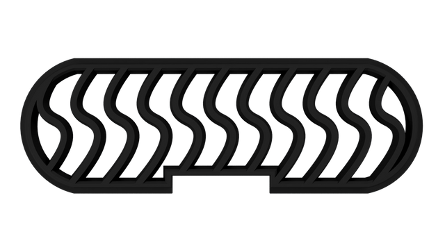
Smooth. But let's add some gloss, just for the sake of shiny, shall we?
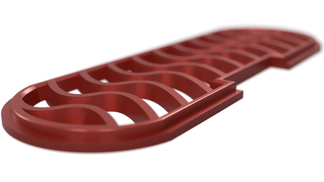
Everything's sexier in go-faster red metallic flake, right?
Conclusion
And there you have it, a walk-through of how to convert an STL mesh into a BRep body in Fusion 360, and some renders to give people an idea of what the finished product might look like.
Along the way we've hit a lot of interesting things about 3D design, 3D modeling, and maybe you'll have found some inspiration to get involved in your own projects as a maker.
If you have any questions or comments, please leave them below. Do you want to see more of this sort of thing? Is there something you want to know how to do in 3D modeling? Would you like some additional focus on 3D printing? How would you like more content about obscure bits of game design?
Let me know.
Until next time, don't do anything I wouldn't do. (That's a list of about three items.)
(Thanks to @techtek for inviting me to contribute to the project.)
Associated Files
Posted on Utopian.io - Rewarding Open Source Contributors
Wow. Top effort, mate. I'm fascinated by 3D printing, but haven't dipped my toes in yet.
We didn't even get to the 3D printing portion of this project, but I think I'm going to have to leave that to someone else. My personal printer doesn't have enough print volume to actually print this piece well.
Though if I'm not mistaken, @techtek is looking at doing some printing of designs that get submitted for the SteemPi case, so there is a chance that this thing could actually see the physical universe at some point.
utopian-io is a steem powered open source collaboration tool.
Maybe we could build a repository for 3D CAD plans, and upvote contributors based on the quality of their work.
Or maybe we can just wait until SMT's are incorporated into existing repositories :)
The models contribute to the SteemPi Project i will add to the SteemPi 3d model repository. It would also be nice to have more open source 3d models that user can contribute to, it would make it possible to have eventually the coolest things, made by the users.
Thingiverse indeed does give these function but the system behind it is limited and not regularly improved. Thingiverse could be much more. but there downsides also brings opportunity for other platforms to improve on.
The recently introduced SteemMakers platform is something im excited about. but for now Utopian and Github seems to be the best way.
Having wrestled around with github a fair amount when working on a number of other projects, the problem with building a repository for CAD designs is that someone would have to be in charge of dealing with them, maintaining the collection, curating them, filtering out the crap – and that is a truly unrewarding job, even if it did pay.
Though arguably that role is already pretty well filled by things like Thingiverse, where you can actually put STEP and IGES files up alongside the STL when you upload a thing. I generally include the parametric files along with the mesh what I send things up to Thingiverse.
If we wait until SMTs are implemented, we'll probably be waiting just outside the heat death of the universe. I've got things I need to do before then.
Thanks for your contribution to the SteemPi project, what a awesome model and write up , i will print and fit the model you made on the case soon!
I'm glad I could be part of the project and help out. It's not often that someone asks me to contribute so when it happens I like to be on top of it and give a solid effort.
Hopefully, people read this and come away with a better understanding of how they can be one of the people who make things, not just uses things. They don't have to but it always makes life a little more interesting to understand how things come into being.
I am happy @techtek found you to do this task. :-) I wasn't able to edit the stl file. What you've showed here looks like it has been through a very complicated process to make it editable. great work!
"nice post"
but yes you have a great brain
GR8
Big, liquid brown eyes and a huge, throbbing, veiny brain. That's all I've got.
But sometimes you just might find, you get what you need.
[Insert musical break here.]
Thank you for the contribution. It has been approved.
You can contact us on Discord.
[utopian-moderator]
Hey @lextenebris I am @utopian-io. I have just upvoted you!
Achievements
Suggestions
Get Noticed!
Community-Driven Witness!
I am the first and only Steem Community-Driven Witness. Participate on Discord. Lets GROW TOGETHER!
Up-vote this comment to grow my power and help Open Source contributions like this one. Want to chat? Join me on Discord https://discord.gg/Pc8HG9x
Nice and informative post ,just like it.
You got a 18.65% upvote from @allaz courtesy of @lextenebris!