stepper Motor speedControl_with_LCD using Pot
Introduction
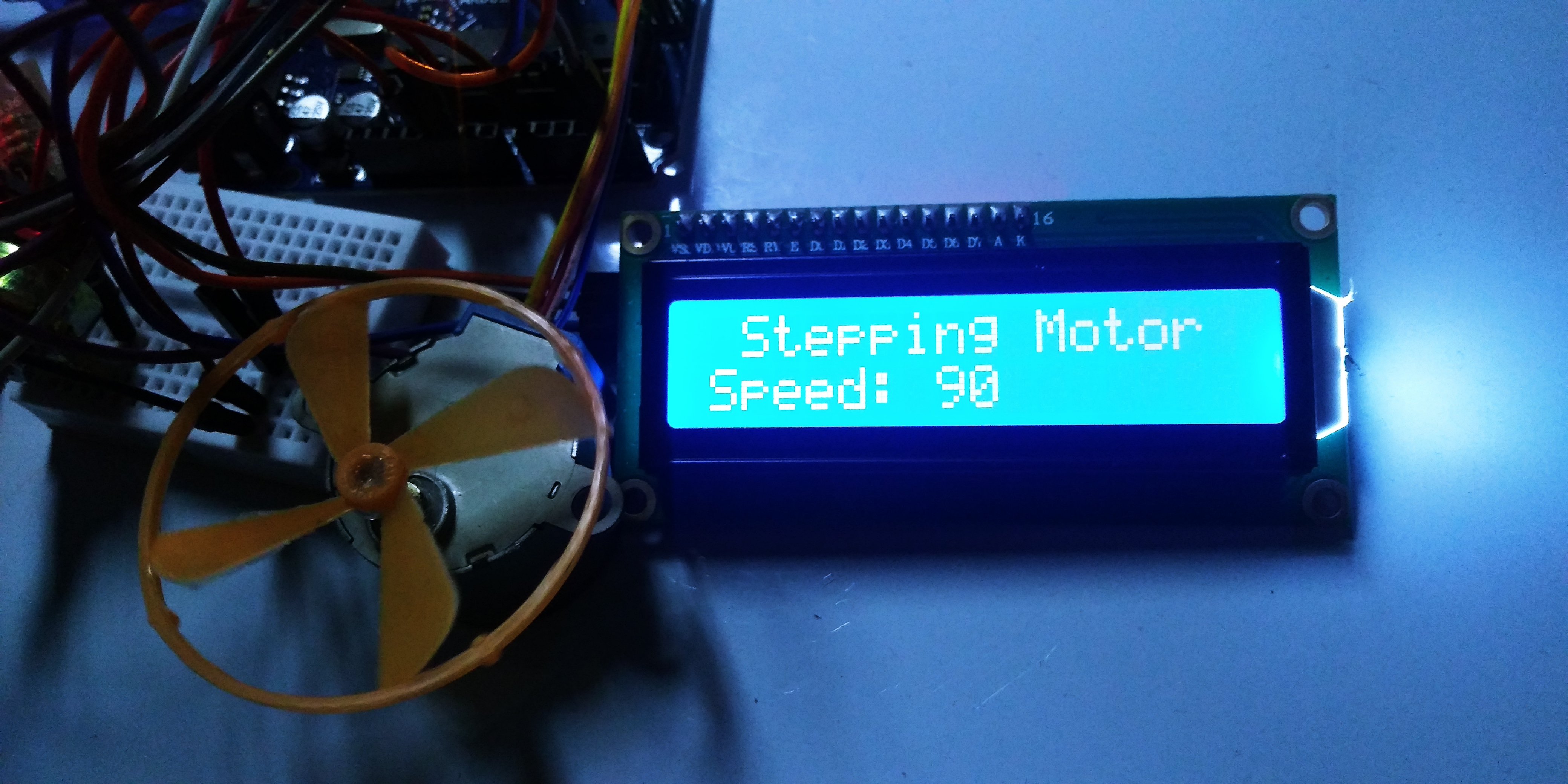
This tutorial is an open source arduino project that teaches how to control Stepper motor using potentiometer i am going to use LCD 16,2 with i2 backpack to display the volume speed of the stepper.
What Will I Learn?
HARDWARE
Step 1: Gather all the Requirements
Requirements
- Stepper motor+ motor driver
- LCD 16,2 with i2c backpack
- Breadboard /optional
- jumper wires
- Potentiometer
- Type B usb cable
- Arduino UNO R3 board
- PC
Difficulty
Either choose between the following options:
- Basic
Tutorial Contents
Experimental Procedures
- Step 2: Build the circuit
The arduino UNO R3
has 14 digital input/output pins (of which 6 can be used as PWM outputs), 6 analog inputs, a 16 MHz quartz crystal, a USB connection, a power jack, an ICSP header and a reset button. 32k Flash Memory,source
codes and programs can be uploaded on to it from the easy Arduino computer program. which makes it a very easy way to get started working with embedded electronics. The name R3 is the third, and latest version of Arduino Uno Board

The 16x 2 LCD with I2C module you will be able to connect the LCD with Arduino board with only two Data cables! The i2c module has a built in potentiometer bakpack for contrast adjustment. The 16x2 display is the set up LCD number of columns and rows ( 16 columns, 2 rows Display ). has 4 build in backpack pins (1) VCC it refers to the power signal of the LCD typically connected to 5volts, (2)GND or sometimes zero voltage, It is also the common connection of the LCD must connect to in one way or another path in order to complete the circuit. (3) SDA and (4) SCL is the i2c serial bus pin it is used to synchronize all data transfers over the I2C bus from the 16 pin of the normal LCD, Both SCL and SDA are connected to analog pin ouputs of the arduino beacasue i2c lines are open drain drivers, means is that the chip can drive its output low.

Connection of LCD to arduino
GND- GND
VCC - 5V
SCL - A4
SDA - A5

the stepper motor converts eletrical power to mechanical like the servo and Dc dynamo motors as its belonging. A step motor has two primary parts; the rotor, the moving piece, and the stator, the stationary piece. The stator contains coils of wire called windings, the pulse generator part can instruct the stepper for accelerattion, run at a speed, decelerate or stop, then the pulse generator must be presented or else the motor will not move.
Connection of stepper Driver to arduino
the stepper driver used ULN2003A to amplify the control signal from the Arduino, it converts pulse to angle displacement. So if you give stepper driver a certain pulse signal, it will drive step motor to a certain angle. you can control the angle the stepper moved by the number of the pulse. And you also can control the speed of the stepper rotate by the frequency of the pulse using a potentiometer which shows in this tutorial.

- INput 1 - Digital pin 9 of the arduino
- IN 2 - pin 10
- IN 3 - pin 11
- IN 4 - pin 12
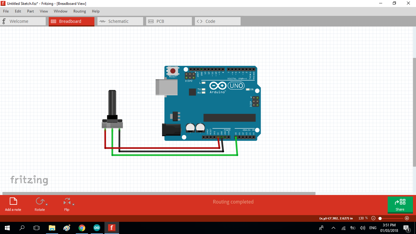
- Connection of potentiometer to arduino
a potentiometer it is device whose resistence or current flow can be manually adjusted by rotating it, Increasing or decreasing the value of resistance controls the amount of current flowing in a circuit. we will this as knob to control the value of the rotating stepper motor. the analog A0 to the midde pin of the pot it send the data signal to arduino and the GND and VCC as power source.
SOFTWARE
- Step 3: Dowload the Software and Libraries
If you’re ready to get started, click on the link below then select the version with your operating system.
Dowload the arduino Desktop IDE: https://www.arduino.cc/en/Main/Software
When the download is finished, un-zip it and open up the Arduino folder to confirm that click yes, there are some files and sub-folders inside. The file structure is important so don’t be moving any files around unless you really know what you’re doing.
Download the liquidcrystal LCD library : https://github.com/fdebrabander/Arduino-LiquidCrystal-I2C-library This library is a modified version of the H. Mario LiquidCrystal_I2C V.2.0 lib.
- Step 4: Include libraries to arduino IDE
Once installed the Arduino desktop IDE. open the software then locate the SKETCH tab at the top of the software, navigate ADD ZIP LIBRARY >> then look for the downloaded libraries in the download folder. SELECT the zip file then wait for the process. include all the libraries fo liquidcrystal display.

- Step 5: Programming
We are using the github repo ; https://github.com/cheon7886/DreamCircuit/blob/master/stepper_speedControl_with_LCD.ino to control the stepper
source code
#include <Wire.h>
#include <LiquidCrystal_I2C.h>
#include <Stepper.h>
const int stepsPerRevolution = 200;  // change this to fit the number of steps per revolution
// for your motor
// initialize the stepper library on pins 8 through 11:
Stepper myStepper(stepsPerRevolution, 9,10,11,12);
LiquidCrystal_I2C lcd(0x27, 2, 1, 0, 4, 5, 6, 7, 3, POSITIVE);
int stepCount = 0;  // number of steps the motor has taken
void setup() {
  lcd.begin(16, 2); // define lcd matrix
  lcd.setCursor(1, 0); // define below message's start point
  lcd.print("Stepping Motor");
  lcd.setCursor(0, 2);
  lcd.print("Speed: ");
}
void loop() {
  // read the sensor value:
  int sensorReading = analogRead(A0);
  // map it to a range from 0 to 100:
  int motorSpeed = map(sensorReading, 0, 1023, 0, 100);
  // set the motor speed:
  if (motorSpeed > 0) {
    myStepper.setSpeed(motorSpeed);
    // step 1/100 of a revolution:
    myStepper.step(stepsPerRevolution/100);
  }
  lcd.setCursor(7, 2);
  // print motor rpm to lcd
  lcd.print(motorSpeed);
}
note: the code from github uses non i2c LCD code on the sketch if youre using LCD with i2c back pack use code above.
- Now, you can see the value of stepping motor rotation on the lcd you can control the speed by rotating the poentiometer.
I hope this Tutorial might help you on your future activity. thank you.
Posted on Utopian.io - Rewarding Open Source Contributors
Hey @lapilipinas, your contribution was rejected by the supervisor @espoem because he found out that it did not follow the Utopian rules.
Upvote this comment to help Utopian grow its power and help other Open Source contributions like this one. Do you want to chat? Join me on Discord.
Wow great technology uses ..At fast i see this technology ..
Thank you for the contribution. It has been approved.
Keep up the good work.
You can contact us on Discord.
[utopian-moderator]
Rejected. Code copied from another site. It can be found in https://github.com/cheon7886/DreamCircuit/blob/master/stepper_speedControl_with_LCD.ino . The text is really poorly written.
You can contact us on Discord.
[utopian-moderator]
Ok.