arduino Digital Dallas Thermometer
Introduction
This tutorial is an open source arduino project that teaches the uses one of the arduino based DigitalTemperature DS18B20 and 16X2 LCD Display to Display the captured temperature data from the sensor, i am going to show you how to make a diy thermometer using this components
What will I learn?
HARDWARE
- Step 1: Gather all the Requirements
Requirements
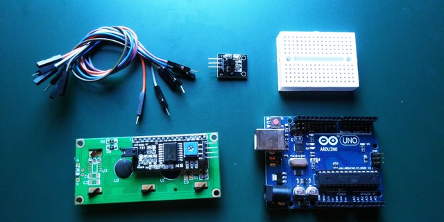
- Temperature Sensor DS18B20
- 16,2 LCD with IIC backpack
- Breadboard
- jumper wires
- Type B usb cable
- Arduino UNO R3 board
- PC
Difficulty
- Basic arduino Project
Tutorial Contents
- Information about the 3 main components
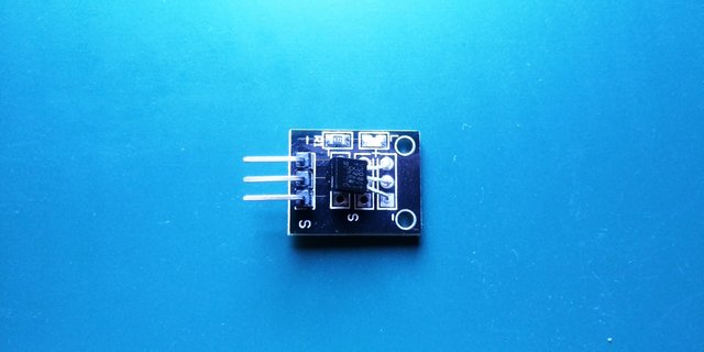
Gather all the components, the Dallas Temperature Sensor DS18B20 this module is used to detect the current room temperature even body heat will captured by this module and can use as thermometer more safe than using a mercuric substance based thermometer, it can use to monitor soil temperature in garden and so far it has held up, these sensor has a 64-Bit Serial number that allows a huge number of sensors to be used on one data pin accurate to the range from -10°C to +85°C.
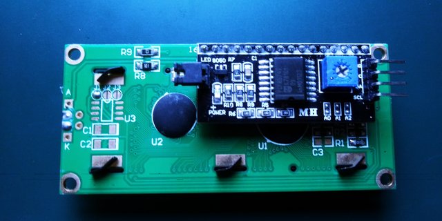
The 16x 2 LCD with I2C module you will be able to connect the LCD with Arduino board with only two Data cables! The i2c module has a built in potentiometer bakpack for contrast adjustment. The 16x2 display is the set up LCD number of columns and rows ( 16 columns, 2 rows Display ).
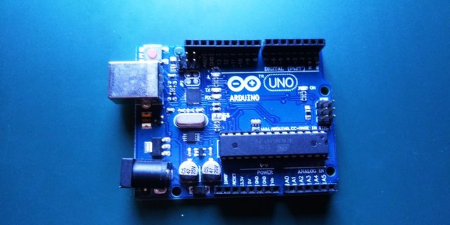
The arduino UNO R3
has 14 digital input/output pins (of which 6 can be used as PWM outputs), 6 analog inputs, a 16 MHz quartz crystal, a USB connection, a power jack, an ICSP header and a reset button. 32k Flash Memory,source
codes and programs can be uploaded on to it from the easy Arduino computer program. which makes it a very easy way to get started working with embedded electronics. The name R3 is the third, and latest version of Arduino Uno Board
Experimental Procedures
Step 2: Build the circuit
- sensor module schematic
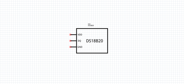
The DS18B20 has built-in 3-pin connectors (1) VCC pin it is normally +5V meaning the devices VCC input is connected to +5V or 3.3V as the main power input pin, (2)GND or sometimes zero voltage, It is also the common connection od the DS18B20 must connect to in one way or another path in order to complete the circuit. (3) S or the sensor this is the data pin that can connect to any of the Digital pin outputs of the arduino board.
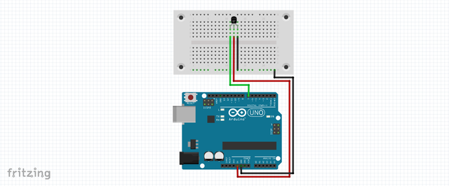
Connections
- VCC - 5V
- GND - GND
- Sensor - 7
The 16X2 LCD display interfaces has 4 build in backpack pins (1) VCC it refers to the power signal of the LCD typically connected to 5volts, (2) GND the zero or common pin it help to complete the current flow of the circuit in path lower then vcc. (3) SDA and (4) SCL is the i2c serial bus pin it is used to synchronize all data transfers over the I2C bus from the 16 pin of the normal LCD, Both SCL and SDA are connected to analog pin ouputs of the arduino beacasue i2c lines are open drain drivers, means is that the chip can drive its output low.
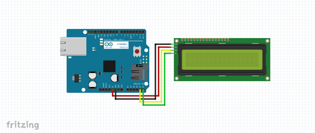
Connections
- VCC - 5V
- GND - GND
- SCL - A4
- SDA -A5
SOFTWARE
- Step 3: Dowload the Software and Libraries
Dowload the arduino Desktop IDE: https://www.arduino.cc/en/Main/Software
Download the : DigitalTemperature DS18B20
DallasTemp library:https://www.arduinolibraries.info/libraries/dallas-temperature
Onewire Library: https://github.com/PaulStoffregen/OneWire
Download the liquidcrystal LCD library : https://github.com/fdebrabander/Arduino-LiquidCrystal-I2C-library
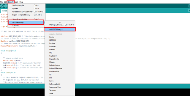
- Step 4: Include libraries to arduino IDE
Once installed the Arduino desktop IDE. open the software then locate the SKETCH tab at the top of the software, navigate ADD ZIP LIBRARY >> then look for the downloaded libraries in the download folder. SELECT the zip file then wait for the process. include all the libraries for onewire, liquidcrystal and dallas lib.
- Step 5: Programming
Add Libraries at the first line of the code define the components library for the DS18B20 add 2 library the onewire and the dallstemp, the liquidcrytal i2c libray is the 3rd line.
#include <OneWire.h>
#include <DallasTemperature.h>
#include <LiquidCrystal_I2C.h>
#include <Wire.h>
Get the i2c LCD address of your module for 16X2 LCD with i2c backpack address is 0x27;
LiquidCrystal_I2C lcd(0x27, 2, 1, 0, 4, 5, 6, 7, 3, POSITIVE);Define the digital outpout of the sensor module to 7 one wire bus respectively
#define ONE_WIRE_BUS 7
OneWire oneWire(ONE_WIRE_BUS);
Pass oneWire reference to Dallas Temperature.
DallasTemperature sensors(&oneWire)At the void setup() function write the command that starts serial connection this method is ran once at the just after the Arduino is powered up. The lcd.begin(16,2) command set up the LCD number of columns and rows. For example, if you have an LCD with 20 columns and 4 rows (20x4) you will have to change this to lcd.begin(20,4).
void setup(void)
{
  // start serial port
  Serial.begin(9600);
  sensors.begin(); // initialize the bus
  lcd.begin(16,2); //initialize the lcd Begin
  lcd.backlight(); //turn on the backlight of the LCD
}
At the he void loop() function this method you want to run the code over and over again. The lcd.print("--message--") command print a message to first column and row of lcd display. The lcd.setCursor(0,1) command will set cursor to first column of second row. print the temperature scale ℉ and ℃ celcius.
void loop(void)
{
  sensors.requestTemperatures(); // Send the command to get temperatures
  lcd.setCursor(0, 0);
  lcd.print("TemC: "); //print "Tem: " on lcd1602
  lcd.print(sensors.getTempCByIndex(0));//print the temperature on lcd1602
  lcd.print(char(223));//print the unit" ℃ "
  lcd.print("C");
  lcd.setCursor(0, 1);
  lcd.print("TemF: ");
  lcd.print(1.8*sensors.getTempCByIndex(0) + 32.0);//print the temperature on lcd1602
  lcd.print(char(223));//print the unit" ℉ "
  lcd.print(" F");
}- Step 6: Upload the code to arduino board
Connect the arduino board to type B usb cable on your computer make sure you choose the correct port and board type on the tools section of the software.
SOURCE CODE
#include <OneWire.h>
#include <DallasTemperature.h>
#include <LiquidCrystal_I2C.h>
#include <Wire.h>
LiquidCrystal_I2C lcd(0x27, 2, 1, 0, 4, 5, 6, 7, 3, POSITIVE);
#define ONE_WIRE_BUS 7
OneWire oneWire(ONE_WIRE_BUS);
DallasTemperature sensors(&oneWire);
void setup(void)
{
Serial.begin(9600);
sensors.begin();
lcd.begin(16,2);
lcd.backlight();
}
void loop(void)
{
sensors.requestTemperatures();
lcd.setCursor(0, 0);
lcd.print("TemC: ");
lcd.print(sensors.getTempCByIndex(0));
lcd.print(char(223));
lcd.print("C");
lcd.setCursor(0, 1);
lcd.print("TemF: ");
lcd.print(1.8*sensors.getTempCByIndex(0) + 32.0);
lcd.print(char(223));
lcd.print(" F");
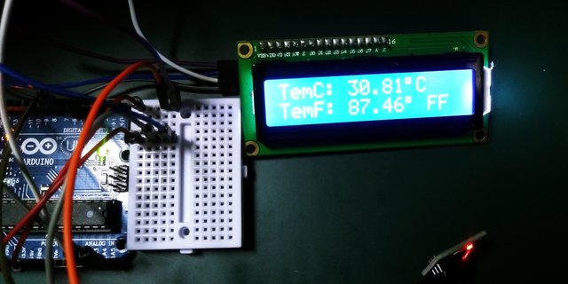
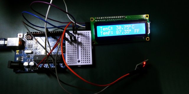
}- Now, you can see the value of current temperature displayed on the LCD.
I hope this Tutorial might help you on your future activity, if you want t buy arduino components ansd learn how to use it, this website might help: https://www.sunfounder.com all images in this post is mine, i appreciate your time reading my post. if you have questions about this tutorial you can drop it below in the comment. thanks you.
Posted on Utopian.io - Rewarding Open Source Contributors
Thank you for the contribution. It has been approved.
You can contact us on Discord.
[utopian-moderator]
Hey @rufans, I just gave you a tip for your hard work on moderation. Upvote this comment to support the utopian moderators and increase your future rewards!
@lapilipinas, Approve is not my ability, but I can upvote you.
Thank you so much for posting, sir. Probably you are into electronics. I am into Telecommunications.
Hey @lapilipinas I am @utopian-io. I have just upvoted you!
Achievements
Suggestions
Get Noticed!
Community-Driven Witness!
I am the first and only Steem Community-Driven Witness. Participate on Discord. Lets GROW TOGETHER!
Up-vote this comment to grow my power and help Open Source contributions like this one. Want to chat? Join me on Discord https://discord.gg/Pc8HG9x