Electronics Simulations #1 | Designing 7 Segment Circuit by using SimulIDE simulator
What Will I Learn?
In this tutorial, utopians :
- will understand the basic working principle of 7 segment IC
- will be able to construct 8-bit segment circuits by using a circuit simulator which is called as 'SimulIDE'.
Requirements
In order to accomplish the tutorial, utopians would need:
- Basic knowledge about circuit design
- SimulIDE circuit simulator software
Difficulty
- Basic
Tutorial Contents
In this tutorial, we will design a simple 7 segment circuit by using the circuit simulator, called as 'SimulIDE'. Basic knowledge about the circutiry will be given before moving into simulation program.
- Episode 1: 7 segment IC
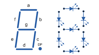
7-segment LED IC, allows to user to display digital data in the form of any alpha-numerical character.
7- segment LED IC, have generally 9 input terminals, 7 of them are connected to circutiry whereas others are ground and voltage feed terminals. Basic structure of of 7 segment LED IC is shown below.
In this tutorial, we are going to construct a basic 7 segment LED IC circuit.
Episode 2: Obtaining the software
In order to download the software, you need to go the following link and install the software by basic installation procedure.
http://simulide.blogspot.com.tr/p/downloads.htmlEpisode 3: Basics of the software
Starting screen of the software is given below
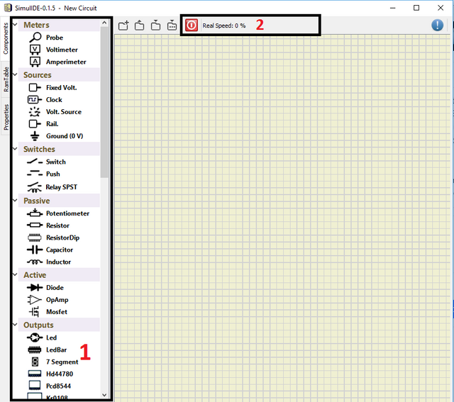
(1) you can find and select the desired component to construct your circuit
(2) by clicking the red button, you can start the simulation
The user can simply choose desired component from the left bar, and drag it into the application window. Connections between the components can be done by simply clicking the desired starting point and end point, respectively.
- **Episode 4: Constructing the 7 segment circuitry **
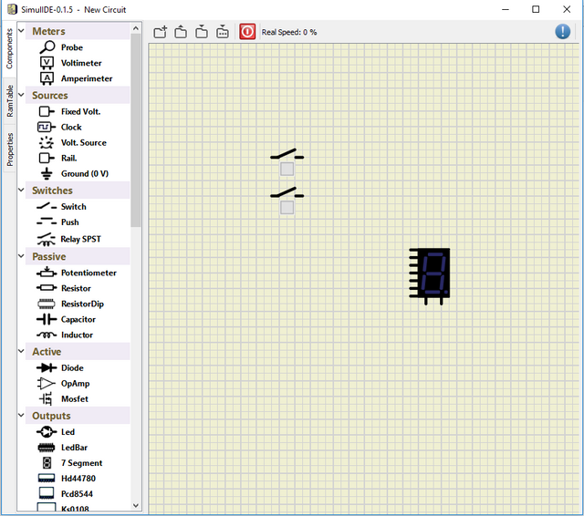
In this part, constructing prodecure will be shown. Firstly, we have to find *7 segment * component on the left table, under the Outputs subtable, and place it to workspace.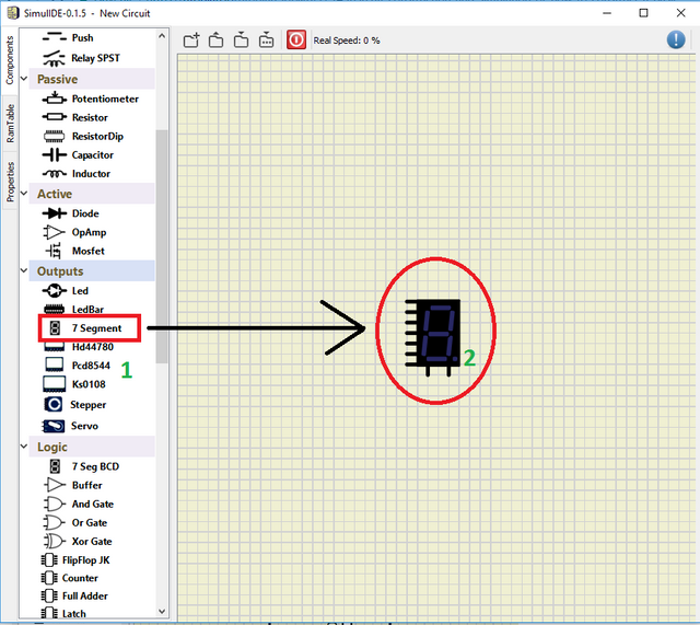
As a second step, we need to put 7 switches to our circuitry, as we have done above, we need to find switch component on the left table, under the Switches subtabpe, and place them to workspace.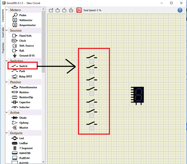
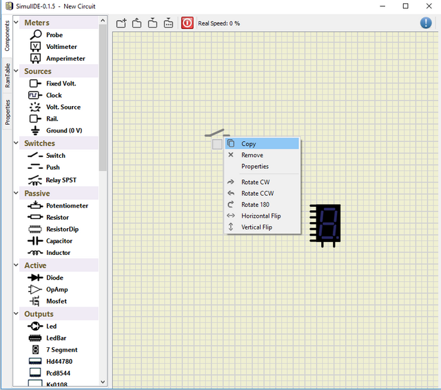
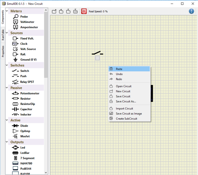
You can add 7 switches individually or take one switch and copy & paste them as shown below
In order to operate remove, undo or redo operations, you can use same procedure too.
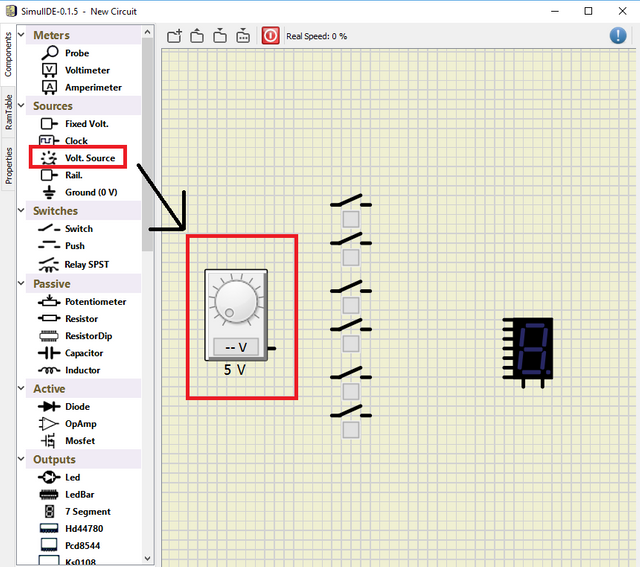
After placing our 7 switches, we need to put our voltage sources, as in the case of switches and 7 segment.
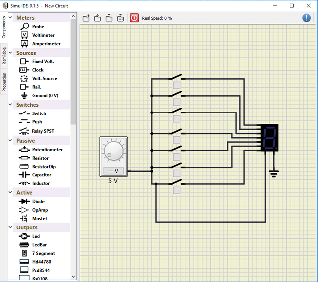
And as a last steps, we need to wire corresponding terminals and the ground. Wiring operation can be done by just clicking the desired terminals, and we need to put ground like other components procedure. Final structure of our circuitry is given below.
Now we are ready to simulate. In order to start simulation, red button should be clicked. You can adjust the voltage value by simply clicking the slider on the source. 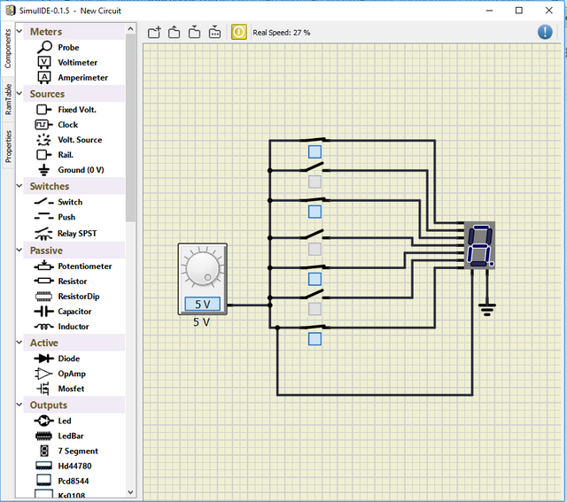
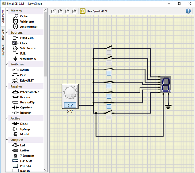
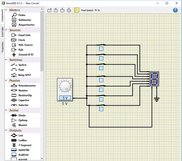
Note that each switch correspond to a piece of the IC, and the user can take desired values by simply adjusting switches.
Posted on Utopian.io - Rewarding Open Source Contributors
@escorn, Contribution to open source project, I like you and upvote.
Your contribution cannot be approved because it does not follow the Utopian Rules.
You can contact us on Discord.
[utopian-moderator]
I have texted you on discord. Could you check it please? Thanks