Qucs simulator for semiconductor electronic circuits: Introduction
What Will I Learn?
In this tutorial the user can acquire the following knowledge:
- Basic management of Qucs as a simulation tool for electronic circuits.
- Analysis of circuits with semiconductor diodes.
- AC signal cuts circuits.
- Transient analysis of a circuit with diodes.
Requirements
- Basic knowledge of circuit analysis.
- Knowledge of basic electronics.
- Basic knowledge of simulators for circuit analysis.
Difficulty
- Intermediate
Tutorial Contents
Greetings the following is a tutorial for utopian, from the account @edagmi. The tutorial is related to the use of the Qucs open source program, to analyze and design electronic circuits with basic semiconductor electronic devices.
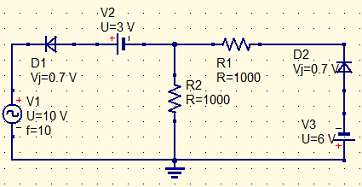
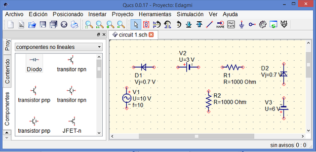
The basic semiconductor device that we are going to use in this first tutorial is the rectifier diode, we are going to perform the analysis of an electronic circuit that displaces and cuts an analog signal. Next, the circuit that we want to analyze is observed.
The following steps describe the use of the Qucs, to perform the simulation of the circuit with diodes:
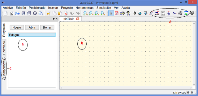
1. We opened the Qucs simulator, it is a tool for the analysis of electronic circuits. In the following image you can see the different Qucs windows, the most relevant ones are described below:
a. Project exploration window (Left of the screen).
b. Schematic window of the circuit (Right of the screen).
c. Tabs to select components. (Tab to the left of the project window)..
d. Menu of connection and execution applications (upper menu bar).
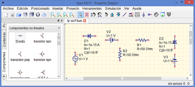
2. We select the components tab and a menu is displayed, where the different components that we will place in the circuit are located, we must select signal or AC source generators, DC sources, resistors and diodes.
3. Each element that is selected is placed in the window corresponding to the schematic circuit, to structure the circuit.
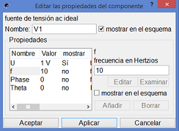
4. By making a clip in the cursor, on each component, a menu is displayed, where we can add the values of the different components of the circuit and modify the characteristics of the element. For the case study, the AC source (V1) corresponds to a 10 volt peak sinusoidal signal and a 10 hertz frequency, to the DC sources (V2 and V3) 3 and 6 volts respectively. The resistors of 1000 ohms and the silicon diode with an internal voltage of 0.7 volts. The image below shows the configuration of the AC source and in the following image the components with their respective values.
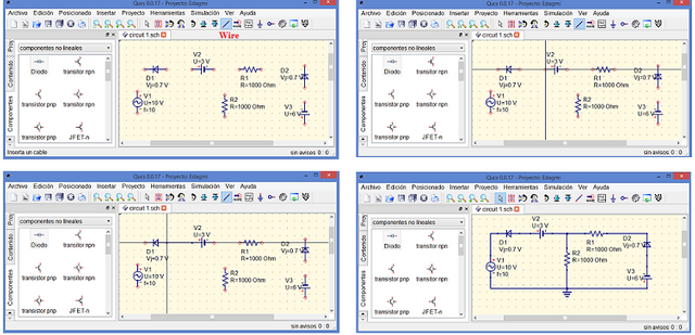
5. To connect the different components, select the wire function, present in the connection and application menu, and perform the following procedure:
a. Select the wiring function.
b. Move the cursor to the terminal of the device to be connected and press enter.
c. Move the cursor to the terminal of the device to be connected and press enter again.
d. Carry out the same procedure between all the terminals of the circuit devices until the
connections are completed.
The graph shows the four previous steps, the earth reference point is added to the circuit.
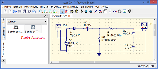
6. We will connect two voltmeters, one in the input signal and one in parallel with the diode D2 in the output signal. The voltmeters can be found in the component menu in the probe function, and the connection is made in the same way as in step 5.
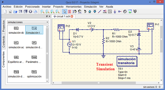
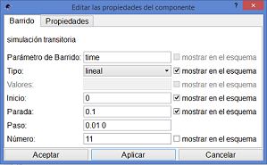
7. To start the simulation, you must select the type of analysis that you need to perform in the circuit, for the case study a transient analysis of the voltage as a function of time is going to be carried out. The simulation function is selected in the component menu and the transient analysis option is selected.
8. The transient simulation must be configured. To do this, you must verify the frequency of the signal, choose the scanning of the analysis, so that the output signal can be displayed correctly.
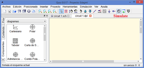
9. We select the simulate option from the application menu. There is a new window with the .dpl extension and the different tools that can be used to visualize the output signal are presented.
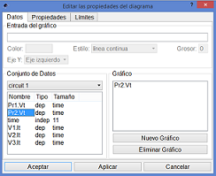
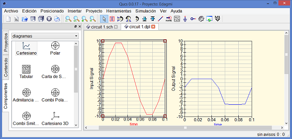
10. In the simulation window, we select two Cartesian graphics to be able to visualize the input signal and the output signal of the circuit cut with semiconductor diodes. In each window you must configure the respective coordinate axes to improve the visualization of the analog signals. You can put the labels of the signal in amplitude equivalent to the peak value of the signal, in our case -10 to 10 volts.
11. Finally we proceed to visualize the signals of entrance and exit of the circuit, observing the displacement of the wave and the rectification of its positive peak due to the diode D1 and next the cut of the negative cycle of the signal due to the polarized cut that produces the diode D2.
This has been the first contribution of the tutorial of use of the Qusc Simulator, for the analysis of circuits with electronic devices. Thanks for your attention.
Posted on Utopian.io - Rewarding Open Source Contributors

Thank you for the contribution. It has been approved.
You can contact us on Discord.
[utopian-moderator]
Hey @edagmi I am @utopian-io. I have just upvoted you!
Achievements
Suggestions
Get Noticed!
Community-Driven Witness!
I am the first and only Steem Community-Driven Witness. Participate on Discord. Lets GROW TOGETHER!
Up-vote this comment to grow my power and help Open Source contributions like this one. Want to chat? Join me on Discord https://discord.gg/Pc8HG9x