Amplitude Modulation Actual circuit Build and simulation in Circuit simulator Applet
What Will I Learn?
- Learn about the Basic Signal mixing in Communication System
- Learn how to construct a diode modulator circuit in Circuit Simulator Applet
- Learn how to construct the circuit in Actual Experiment
- Learn About how Amplitude Modulation Works
Requirements
- Circuit Simulator Applet
- Electronics Components: Wires, Resistors: "1K ohms - 3pcs", Capacitor: "220nF & 1uF ", Inductor:"2.5mH - 1pc", Diode: "1N4001 or 1N4007 - 1pc"
- Electronics Laboratory Equipments: Digital Trainer, Oscilloscope, Digital Multi-Testers and
two Function Generators
Difficulty
- Intermediate
Tutorial Contents:
Abstract
In this tutorial we are able to know how a signal is being mix through the use of diode modulator circuit the main purpose of this circuit is to perform the process called Modulation where in this case we are modulating the amplitude of the signal this is commonly termed as an Amplitude modulation, this process is done in order for the information to be injected to the higher frequency carrier for the propagation of signal in the air as a radio waves.
We are going to do this using Circuit Simulator Applet and an Actual circuit build for us to prove that the theory that we are working are applicable in reality, application of this theory would be in the field of communication or Radio Broadcasting.
Constructing the Actual circuit
Schematic Diagram:

1.) Connect the actual electronic components based in the schematic diagram above.
(below is the finished connection of the circuit)

2.) After constructing the circuit apply it with two AC source with different frequencies, higher frequency and a lower frequency based in the schematic diagram, the higher frequency is the Carrier signal and the lower frequency is the information signal.
Carrier Signal:

The carrier signal is 6kHz should be greater than the information signal for better modulation this will be the signal that will carry the data for transmission (in radio broadcasting this will be propagated in antenna as radio waves) which is the information signal.
Information Signal:

Information signal could be an audio source if we are dealing with broadcasting or a voice captured by the microphone. (in real application, since this is an experiment we are just using a fixed frequency source our human voice has a lot of frequencies generated as sound waves. ).
3.) Connect the probe of oscilloscope to the output of the circuit to see the resulting waveform.

After connecting the circuit you will see a new Waveform called AM Envelope:
AM Envelope:
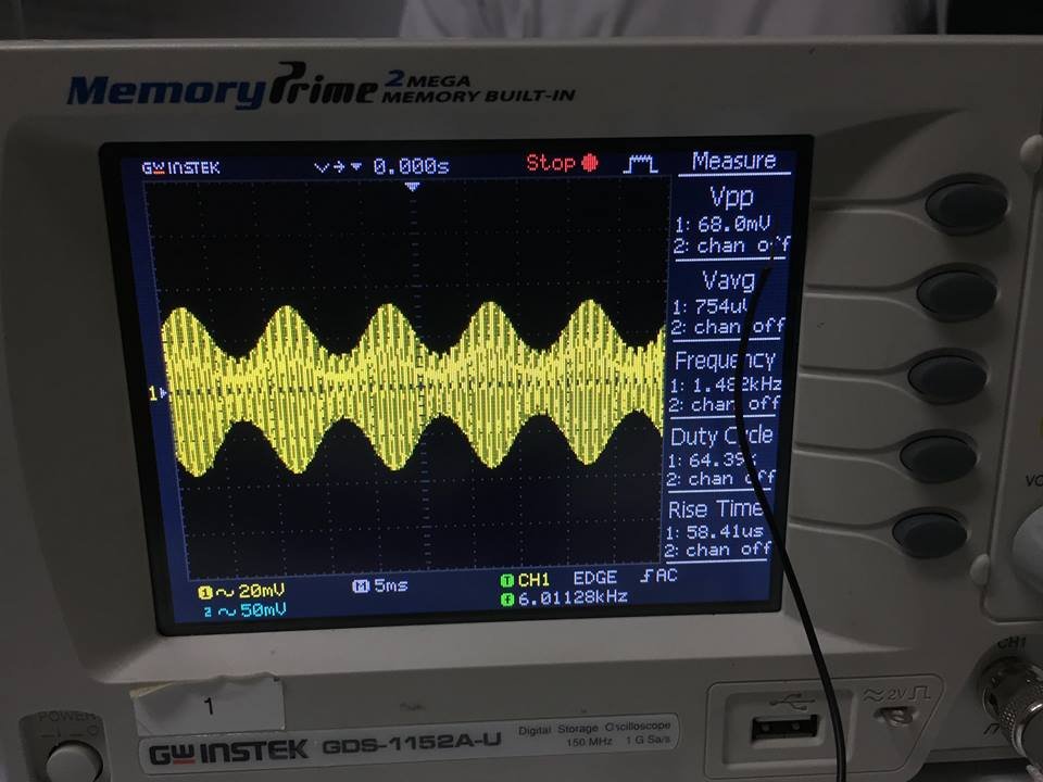
This waveform is being generated by the combination of the 2 signal or frequency that we had inputted which is the carrier and information signal this process is called AMPLITUDE MODULATION.
AM Envelope Adjusted time/div:

In AMPLITUDE MODULATION the amplitude of the carrier signal is being modulated in proportion to the information signal, the sine wave formed in the amplitude of the carrier is the information signal it is located in positive half cycle and also in negative half cycle, this resulting waveform is to be transmitted and receive by the receiver circuit its main component is diode detector.
Constructing the circuit in Circuit Simulator Applet
Construct the circuit based in schematic diagram above.
Select the components needed to construct the circuit, you can select the components needed in that area being box

Place all the components needed in the screen for connection, you can also change or edit the values of the components by just double clicking it.(image below has not yet edited to the schematic value)

Add two frequencies as our input the higher frequency and the lower frequency


After putting all the components needed in the circuit and the input sources connect the components based in the circuit diagram above(schematic), click add wire to connect the components you can also stretch it.
When the circuit is done click Run/STOP to start simulating. you will then see the current flow and voltage of the circuit how it behaves as the two signals mixed in the diode modulator circuit.
(final circuit)


And finally we are done with our modulation tutorial this would be great for students and young electronics hobbyist who want to learn about the basic of signal mixing.
Curriculum
Posted on Utopian.io - Rewarding Open Source Contributors
Your contribution cannot be approved because it does not follow the Utopian Rules.
Related Rules:
Clarifications and Suggestions:
You can contact us on Discord.
[utopian-moderator]
Hey @roj, I just gave you a tip for your hard work on moderation. Upvote this comment to support the utopian moderators and increase your future rewards!