TUTORIAL ON HOW TO TURN WASTE TO COOKING GAS (BIOGAS)

Repository
https://github.com/abduloniz1/biogas/tree/master
Biogas is a Microorganisms who thrive in the absence of air digests, the organic material and releases a mixture of gases. The gases thus produced contains mostly methane along with other gases like Carbon dioxide, Nitrogen and Hydrogen Sulphide in small quantities. This process is known as anaerobic digestion. Methane is a colorless and odorless gas and is highly flammable. (It is Hydrogen Sulphide that smells bad) Methane is not poisonous. Methane along with other gases occurs naturally in swamps, waste dumps and even in-home toilets in the septic tank. Due to its highly flammable quality, it can be used as fuel. But capturing the methane from the atmosphere is very difficult as it is lighter than air. The Biogas Digester or Biogas Plant we see here is a device which helps us in collecting this gas and use it as fuel.
Biogas Plant
You can see the opened-up prototype of a B plant
Step needed to build biogas
THE STEP BY STEP ON HOW TO BUILD A BIOGAS PLANT (TURNING WASTE TO COOKING GAS)
We have about 35 stages and about 175 well detailed picture for the completion of this kind of Biogas plant size......Right now I will start from the first stage to tenth stage, The remaining stage will be post here as soon as its ready.
In the prototype picture above, want you to understand some terms about building a Biogas plant, In the picture above, the white container is called: THE GAS HOLDER; The container holds the methane gas we are using for cooking, The Orange Container is called: THE DIGESTER, it holds the waste, THE YELLOW HOLES: Allows the passage of the gas to the burner. THE BLUE PIPE is the OUTLET PIPE, the red cap you see on the white container, IS WHERE YOU WILL BE FEEDING YOUR PLANT WITH WASTE, the ash pipe, is a support pipe......Though there are still other material needed like THE BALL VALVE, ADHESIVE MATERIAL for bonding, and other PLUMBING MATERIAL which you will know in other stages.


Step 1: Selection of Tanks
Before selection of tanks, I need to consider how much of digestible kitchen and garden waste I could collect every day for feeding the tank. In my case I can easily collect between 3.5 to 4 kilograms of waste from kitchen and home garden. This quantity will be sufficient for a biogas plant with 700 to 800-liter capacity digester tank. Since only 750-liter capacity tanks are available in the market, I have selected a 750-liter tank to be used as the digester. A simple thump rule for biogas plant for home use is 5 kilograms of waste needs a 1000-liter capacity digester. Now for the selection of gas holder tank, I
need to consider the following before buying the tank:

Step 2: The method to be used:
The model I am building is with a floating type gas holder tank. That means the gas holder will move up and down based on the amount of gas inside. So, the gas holder tank should fit inside the digester and also should have minimum difference between their width as this will reduce in loss of gas through the sides. During market search, I found that the 500 liters capacity tank will meet the requirement, having a width difference of about 100 mm, that means 50 mm on each side. So, I have decided to use the 500-liter tank as gas holder, which will have an up- and- down movement inside the digester using guides. Some designs cater for a water seal between the digester and gas holder, but in my case that will considerably reduce the capacity of the digester. However, the gas loss through the sides will be very marginal with respect to providing a water seal and reducing the capacity.
Step 3: Other Materials Required
In addition to the tanks, I have utilized the following PVC parts PVC Door elbow 120 mm dia one number to be used for feeding waste PVC pipe 50 mm dia 300 mm long to be fitted with digester for slurry outlet PVC pipes 32 mm dia 250 mm long 4 pieces to be fitted with digester for guide system PVC pipes 32 mm dia 1000 mm long 4 pieces for guide system PVC pipes 12 mm dia 1000 mm long 4 pieces for guide system and stabilizing gas tank PVC pipe 120 mm dia one piece to be used for waste feeding PVC cap 120 mm dia for the waste feed pipe PVC pipe 50 mm dia about 5 meters for the slurry outlet system PVC bend 50 mm dia one piece for the slurry outlet system PVC 32 mm dia threaded couplers 4 pieces to be fitted with gas tank for guide system PVC 32 mm dia plain couplers 4 pieces to be fitted with digester for guide system PVC Elbow reducer 32 mm to 12 mm 4 pieces for the guide system Items required for the Gas pipe line is given
separately in Step below.


Step 5: Tools Required
You can see here that construction of this plant does not require many tools. These are list of tools I have used:
A hacksaw with frame
A single sided hacksaw blade
A sharp knife
A medium sized hammer
Set of spanners to tighten the gas pipe connectors for crimping the connectors with the ends of gas pipes, I got assistance from the shop from where I bought the gas pipes. They helped me with their Hand crimping equipment as per my requirement.


Step 6: Preparation of Gas Holder Tank
The 500-liter capacity tank is required to be cut at the top. The visible top ridge will be used as guide line to cut the tank Using a sharp knife make a slot along the line Now you can insert a hacksaw blade in the slot and cut along the ridge the hacksaw blade gets very hot. Wrap the end with a piece of cloth
Cut through the ridge and remove the top cut portion from the tank

Step 7: Preparation of Digester Tank
The top portion of the digester tank also needs to be cut and removed. However, the width of cutting should be just enough for the free movement of gas tank Place the removed top portion of gas holder on top of digester tank Leave about 20 mm on all sides and mark the guide line for cutting Using a hacksaw, cut slots on top of projected portion of digester tank Now use a hacksaw blade to cut along
the guide line and remove the top Finish the cut edges with sand paper

Step 8: Fixing the Feed Pipe to the Digester Tank
The 120 mm dia door elbow need to be fixed at the bottom of the digester tank Place the elbow and mark the cutting line make a slot along the line with a sharp Knife Insert the hacksaw blade in the slot and cut along the guide line Insert the Elbow in place Seal with M-seal epoxy compound on both outer and inner sides of the tank


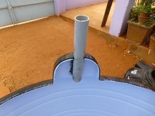
Step 9: Fixing Slurry Outlet Pipe with the Digester Tank
The 50 mm dia 300 mm long pipe is to be fitted at the top of digester for the slurry outlet Place the pipe on top portion of digester tank opposite to the feed pipe Mark the cutting line Using a sharp knife cut along the guide line and remove the cut piece Insert the slurry outlet pipe and seal with M-seal epoxy compound from both sides of the tank You can cut and remove the extra projection inside tank if required. Otherwise leave as it is


Step 10: Fixing the Guides Over Digester for the Movement of Gas Holder Tank
Some sort of guides are to be provided for the easy up-and-down movement of gas holder tank. We will use the 250 mm long 32 mm dia pipes for this. There are six projected portions on top of the digester. The slurry outlet pipe and waste input pipe are in alignment with two them opposite to each other. Leaving these two we will fix 32 mm pipes on other four projections. These pipes will be extended after placing the gas holder tank. Place the 32 mm dia pipe on top of projections and make a mark Using a hacksaw cut and remover square portion of the marked area. Insert 32 mm dia pipes on all these cut portions and fix with M-seal epoxy compound After the compound is cured cut and remove excess leaving about 25 mm projection.
This is my first contribution to utopian.io, hope my project is viable to the platform.
Thanks for reading the project, our next step will be ready as soon as possible.!
Turning waste into cooking gas!!
I have held about this kind of project before but i have not come across how the set it up.
I will try as much as posible to follow it up.
Thanks @abduloniz
Thank you.
Nice project
Thank you @iseac