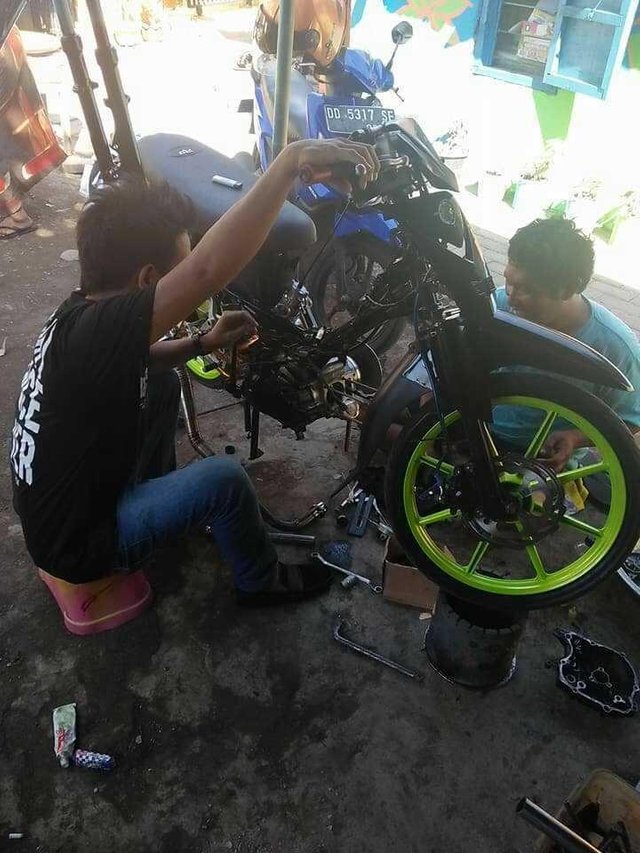
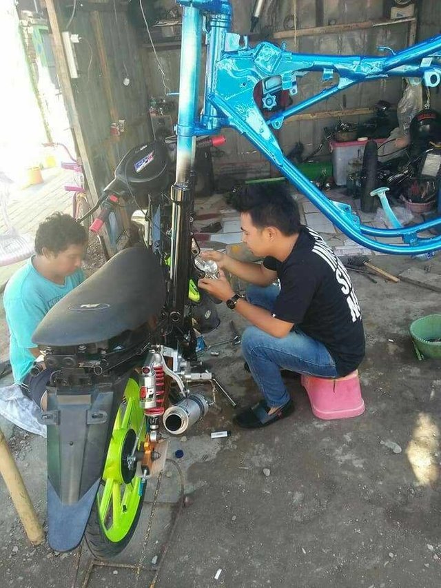
Disassemble Pairs of Motorcycle Engines Properly and Correctly
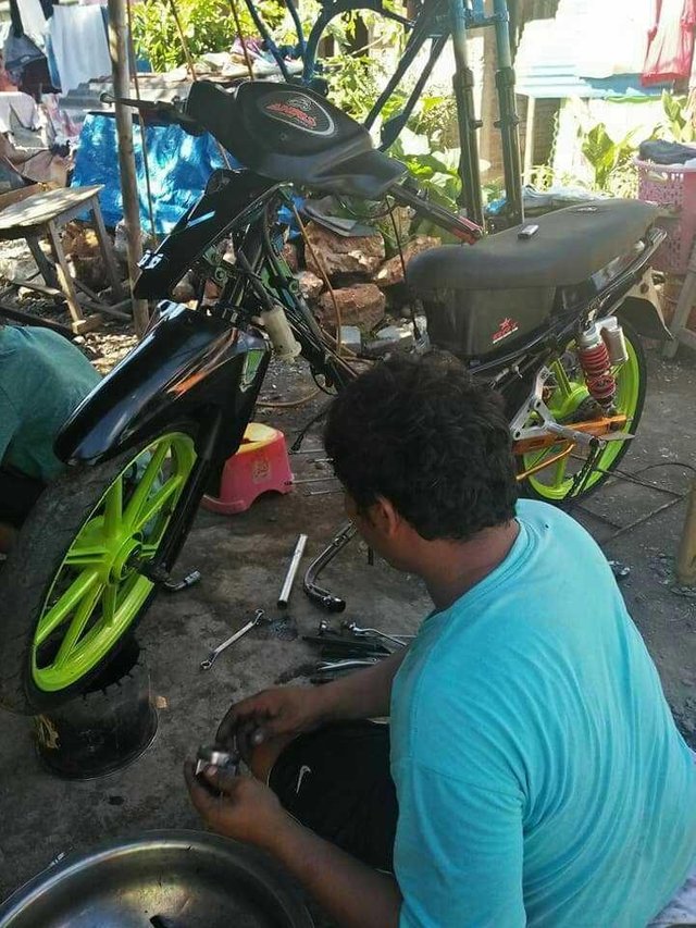
In this all-sophisticated era many of us are still Gaptek alias (stuttering technology) about the problem of pairs of machines and engine settings to improve our motorcycle performance so much better, here I am as a humble article writer is willing to share knowledge about how disassemble and install the machine properly, since also my hobby in motor machines especially in the brand HONDA.
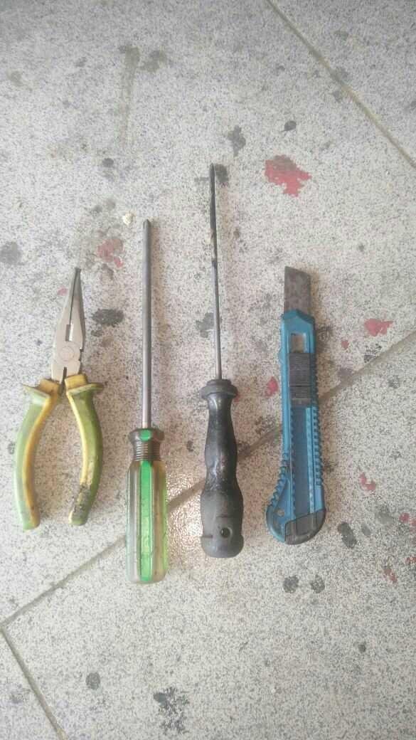
First in the required a technician or what we often call Mechanics must have adequate tools such as my example as follows:
- Tang
- Screwdrivers plus (+) and minus (-)
- Hammer
- Wrench (8.9,10,12,14,17,19,22,24)
- Ring lock (8,9,10,12,14,17,19,22,24)
- Tap screwdriver 1 set
- Lock shok 1 set
- T key 1 set
- Tang circlip
- Filler gauge
- magnetic motor opening traker
- Special tools sprocket nut openers
Steps to unload honda motorcycle engine type 100cc cub
STEP 1: Cylindrical block parts and cylinder head
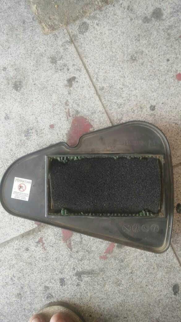
A. Unload Carburator by removing 2 pieces of 10mm bolts using 10 ring locks
B. Remove the exhaust and spark plug and then release the gear timing chain by opening the gear timing cover. Keep the marker on the gear timing with the coil on the cylinder head and make sure it is neutral or compressed by rotating the magnet nut using the 14mm T key toward the front and look at the magnet of the letter (T). open two timer fastening bolts on the noken axle, then remove the timing teeth outwards.
C. Open the mounting bolt on the left side of the cylinder head features "bolt plot and in the center there is a plus screwdriver (+) using a 10 mm spanner".
D. Open the 4 cylinder head fastener nut just behind the front wheel, using a 10 mm shok key
E. Remove the cylinder head from the cylinder block
F. Open the timer roller bolt by using a 10mm T key, on the cylinder block, remove the timing roller to the left.
G. Remove the cylinder block from the crank case forward
H. Remove the piston pin retaining beam using a small minus screwdriver or using long-mouth pliers
I. unload the piston pin
STEP 2: Magnet Part
A. Open the left magnet tub using the 8 mm T key, but do not forget to open the gear pedal first with a 10 mm wrench.
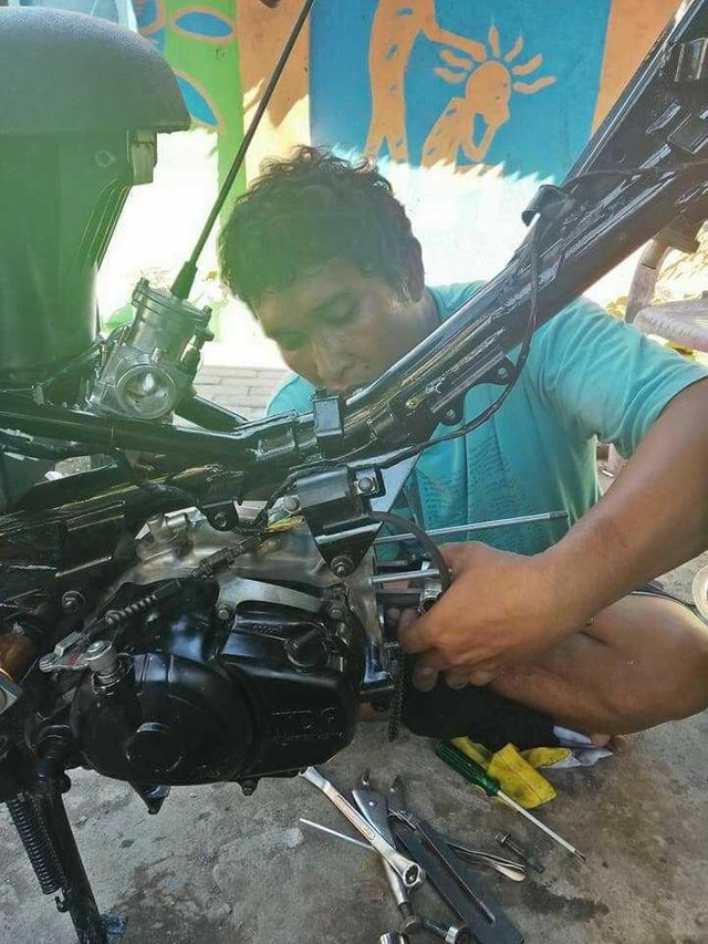
B. Remove the magnet nut release by using a 14 mm shok key, and use special tools or often called a magnetic traker to remove the magnet. see picture below:
C. Remove the stater gear by using criclip pliers and stater chain rubber using a minus screwdriver (-) slightly prying it
D. Remove the magnetic spi using a minus screwdriver and a hammer, scoop up the screwdriver and grip the screwdriver until the spi is released.
D. Remove the magnetic spi using a minus screwdriver and a hammer, scoop up the screwdriver and grip the screwdriver until the spi is released.
E. Release the stater gear simultaneously
F. Unlock the fastener on a large timing chain cover using a tap screwdriver
H. Remove the timing chain cover, then remove the small timing wheel and remove the timing chain from the timing teeth.
STEP 3: Coupling Section
A. Open the oil exhaust bolt by using the 17mm shok key and the oil container into the container already provided
B. Open stand pedal bolts on the machine as much as 4 pieces using a 12mm shok key
C. Open the kick stater using a 12mm ring lock
D. Open the clutch tub bolt by using 8 mm T key less than 10 pieces
E. Then gently remove the clutch.
F. Open oil filter screw on sprocket or double clutch of 3 pieces with 8mm T key or with a tap screwdriver, then remove the filter cover
G. Remove the safety claws on the spore binding nut by prying towards the right or left so that it no longer holds the binder nut.
H. Open the binder nut using special tools (it is recommended not to use chisel or that can make the shaft baling)
I. Open 2 pieces of oil container bowl bolt on a clutch canvas housing using a 10mm T key
J. Remove the bearings on the clutch canvas housing.
K. Open the home clutch canvas binder nuts using spatial tools
L. Remove the clutch house and sprocket set simultaneously with both hands on the outside.
STEP 4: Removing the crank case
A. Remove the front gear bolt bolt by using a 10mm T key
B. Remove the bolt bolt machine using the shirt key 14mm as much as 3 pieces and the machine is ready to be removed from the frame
C. Remove on the kick stater axis using circlip pliers.
D. Open the crank case bolts approximately 8 to 10 bolts using the 8mm T key on the left side of the crank case
E. Remove the crank case
F. Remove the crankshaft from the crank case
G. Release the Gear ratio simultaneously outward and wrap it up if you do not want the ratio to be scattered later on.
At the time of installation
do the opposite "put it with the groove that I made earlier with the process reversed",
whichever is first disassembled will be installed later.
#Easy is not it ??
So the information I can provide, may be useful for readers who want to do the demolition of the machine itself, if there are still shortcomings in the writing on my blog @vanirfan this is wrong I apologize because humans are not perfect.
Thanks.
This is Great.... I really wish you could add more pictures to illustrate the steps so we could get a clearer understanding. But anyways, you have got a great post here.
Okay thanks friends, Wait for my next tutorial friends :)
Ngebengkel