3d modelling Tutorial - Starwars 3-CPO head - Part 1
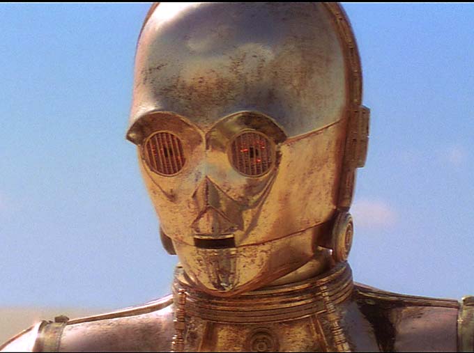
Image source: starwarshelmets.com
In this post I will show in easy to follow steps how to model the Starwars droid C-3PO in Blender.
Due to the size of the work I will split the post in two parts.
1. Add reference image
- Search the internet for a good reference image that shows the front and side profile of 3-CPO.
- In Blender press the N key to open the "Properties window" and scroll down Background image.
- Checkmark Background image and press the "Add Image" button.
- Select the front image you saved on your hard drive/cloud. Under Axis be sure to select Front (otherwise the image will be shown on all orthographic views).
- Do the same for the side image and select the Right view under Axis.
- Tip: The short keys for the front view is 1 and for Right view 3. To switch between perspective and orthographic view press 5.

2. Add a Mesh (UV Sphere)
- Now that the images are in place we can start to add Meshes to start modelling. Since the head has a round shape the suitable Mesh to add is the UV Sphere.
- In Blender a new Mesh (Object) is added where the 3d cursor is. Let's first make sure the 3d cursor is at the center. Press Shift+S to open the Snap menu and select Cursor to Center.
- Than press Shift+A to open the Add menu, select Mesh and than UV Sphere.
- In order to Scale the Sphere down, Press the S Key and move the mouse until the right size.

3. Do half the work, use Mirror.
- In order to safe time and work efficiently lets delete some geometry and mirror it so we only need to work on one side.
- Press the TAB button to switch to Edit Mode
- Press the Z Key to switch to Wireframe View, this view allows us to select also the hidden edges and points (vertices).
- Press the B Key to select the Box select tool. Than select all points at the lower half of the sphere.
- Press the X Key which opens the Delete Menu and choose Vertices.
- Do the same and delete the left upper half.

- With the mesh being cut away we can use now a Modifier to Mirror the remaining Mesh.
- On the right side (Outliner) select the Wrench icon and press Add Modifier.
- Under Generate select Mirror.

4. Start to bring the head into shape.
- In Edit mode select the point (vertices) and move the mesh along the images.
- Use the Proportional Editing tool O Key to move the related mesh as well.
- With the mouse wheel you can determine the size of the proportional editing (white circle) and how many related vertices are impacted.

- In order to bring the Mesh down we can use the Extrude tool (E Key)
- First select the edge tool than hold ALT and click with Right mouse to select all related edges (Ring select)
- Now Press the E key and drag the mesh down.
- With pressing Z Key you can restrict the Extrude direction to be vertical. (Along the Z Axis)
- Use the S Key to Scale along the way.
- Repeat a couple of time.

- After you edited the head shape along the front and side view using the vertices, your head should look similar to this.
Please note that no smoothing is applied at this point.

So cool!