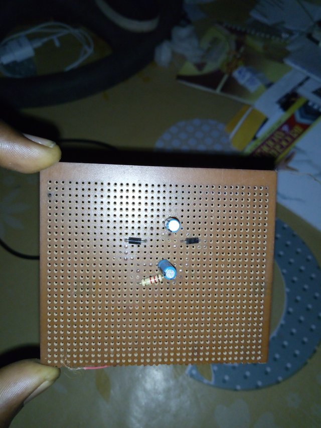
The voltage doubler
The Voltage Doubler
As its name implies, a Voltage Doubler is a voltage multiplier circuit which has a voltage multiplication factor of two. The circuit consists of only two diodes, two capacitors and a resistor. This simple diode-capacitor pump circuit gives a DC output voltage equal to the peak-to-peak value of the sinusoidal input. In other words, double the peak voltage value because the diodes and the capacitors work together to effectively double the voltage.
DC Voltage Doubler Circuit
So how does it work. The circuit shows a half wave voltage doubler. During the negative half cycle of the sinusoidal input waveform, diode D1 is forward biased and conducts charging up the pump capacitor, C1 to the peak value of the input voltage, (Vp). Because there is no return path for capacitor C1 to discharge into, it remains fully charged acting as a storage device in series with the voltage supply. At the same time, diode D2 conducts via D1 charging up capacitor, C2.
During the positive half cycle, diode D1 is reverse biased blocking the discharging of C1while diode D2 is forward biased charging up capacitor C2. But because there is a voltage across capacitor C1 already equal to the peak input voltage, capacitor C2 charges to twice the peak voltage value of the input signal.
The advantage of “Voltage Multiplier Circuits” is that it allows higher voltages to be created from a low voltage power source without a need for an expensive high voltage transformer as the voltage doubler circuit makes it possible to use a transformer with a lower step up ratio than would be need if an ordinary full wave supply were used