Project 4 - "RUNNING LIGHTS" using 7493 IC Binary Counter and 74154 Demultiplexer IC - Electronics
What Will I Learn?
By finishing this tutorial:
♦ The reader will able to create Running lights without the used of arduino
♦ The reader will understand the functions of the circuit and components being used
♦ The reader will be more flexible in using different softwares in components simulations and testings
♦ The reader can be creative in applying this project in the future
Introduction
In this tutorial post, we are going to make RUNNING LIGHTS that can be used in different ways like store attractions or simply to beautify anything depends on your creativity and desired application. I made this tutorial post to share another ways of making electronic project not as usual using an arduino. The main components here are 7493 IC and 74154 IC. 7493 IC which is also known as binary counter, will provide a series of changes as pulses was received from the timer circuit while 74154 Demultiplexer will give corresponding output based on the given proper controlled input signal.
You can read more about Running Lights Here

Requirements
Materials needed:
♦ 7493 IC Binary Counter
♦ 74154 Demultiplexer IC
♦ Breadboard (In making Circuit)
♦ Copper Clad Board (Optional)
♦ Jumper wires
♦ Resistors (6pcs of 220 ohms and 1pc of 10k ohms)
♦ Capacitor (10 micro farad)
♦ Potentiometer (100k ohms)
♦ Battery (5v to 9v)
Software
♦ Fritzing application
♦ Proteus - Direct Download Here
Short description for the materials
7493 IC Binary Counter ⟶ This ic is responsible in producing a proper controlled signal to the next stage in 74154 Demultiplexer IC.
74154 Demultiplexer IC ⟶It is also called Line DECODER and use to expand an input signal to different output signals.
Breadboard ⟶ It is an electronic tools for experimental purposes where you can make Circuit by experimentally mounting the components, wires and connections temporarily.
Copper CladBoard ⟶ It is a board in different sizes where you can sketch your design circuit connections and etch it for permanent layout and permanent circuit connections.
Jumper Wires ⟶ Wires use for connections to be properly connected and to organize those connections clearly.
Resistors ⟶ It is an electronic components responsible in controlling the amount of electrical flow in a certain part of Circuit for the desired amount of voltage.
Capacitor ⟶ This is an electronic components which stores voltage in electric field.
Difficulty
♦ Intermediate
Tutorial Contents
Now, I'm going to teach you how to make our RUNNING LIGHTS Circuit using a software called Proteus.
Part I. Schematic Diagram
❶ Open the Proteus Software
.png)
❷ Click on "New Project"

❸ Find and select all the needed Components
The picture below only shows the main components since the other components are very easy to find by just typing their specific name like resistors, capacitor and LEDs.

All Proteus Components needed

❹ Assembling the components
First Stage
Actually, The circuit of the project has 3 major stages or parts. The first one is the picture below which is the NE555 area which serves as the timer of the circuit produces pulses depends upon the value combination of resistors.
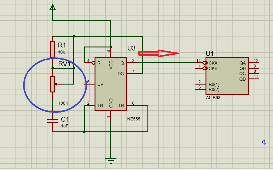
The purple circle is the Potentiometer which can be adjusted to produce a certain speed of the frequency. As the resistance increases, the frequency per seconds will becomes slower or smaller while the red arrow represents for the output of this stage.
Second Stage

In this stage, Referring to 7493 IC, its CKA or clock input receives the pulse signal from the first stage or the timer circuit stage.
To breifly understand its pin configuration see table below
7493 (4-bit binary counter)
| Pin | Symbol | Description |
|---|---|---|
| 1 | CKA | clock input, 2nd, 3rd and 4th section (high-to-low edge-triggered) |
| 2 | R0 (1) | asynchronous master reset |
| 3 | R0 (2) | asynchronous master reset |
| 4 | NC | no connection |
| 5 | Vcc | supply voltage |
| 6 | NC | no connection |
| 7 | NC | no connection |
| 8 | QC | counter output |
| 9 | QB | counter output |
| 10 | GND | ground |
| 11 | QD | counter output |
| 12 | QA | counter output |
| 13 | NC | no connection |
| 14 | CKB | clock input, 1st section (high-to-low edge-triggered) |
Third Stage
The main component of the third stage is the 74154 Demultiplexer IC. The simple theory behind DEMUX is just to decode four input signals (signals from 7493) into 16 output signals
This component is very important to produce many outputs from few input frequency signals and for us to make many combinations of led designs.

Notes:
♦ In wiring the circuit in the real world, make sure not to short the leads of LEDs and resistors because this could damage the Integrated Circuit (IC) permanently.
Part II. Circuit Construction of the Running Lights in BreadBoard
❶ Open the fritzing Software - In this part I'm using other type of electronics software for testing components and circuits for Flexibility purposes 🔥. Also, this procedure is for realistic testing of components connected to each of them in the application of Running lights.
.png)
Beta version can also do the same as the original software
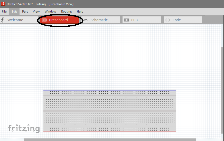
❷ Click on the breadboard
❸ Find and ready the components being needed

❹ Arrange or assemble the components the same connections like the circuit we recently made
First Stage

I show this ways to easily analyze and troubleshoot the connections. This will also to guide everyone for the connections to be properly connected
Second Stage

The same procedure as the first stage, just follow the circuit guide and just be aware on short circuit to avoid any damage or malfunctions to the circuit.
Third Stage

The actual Running Lights Project
PCB COMPONENTS SIDE
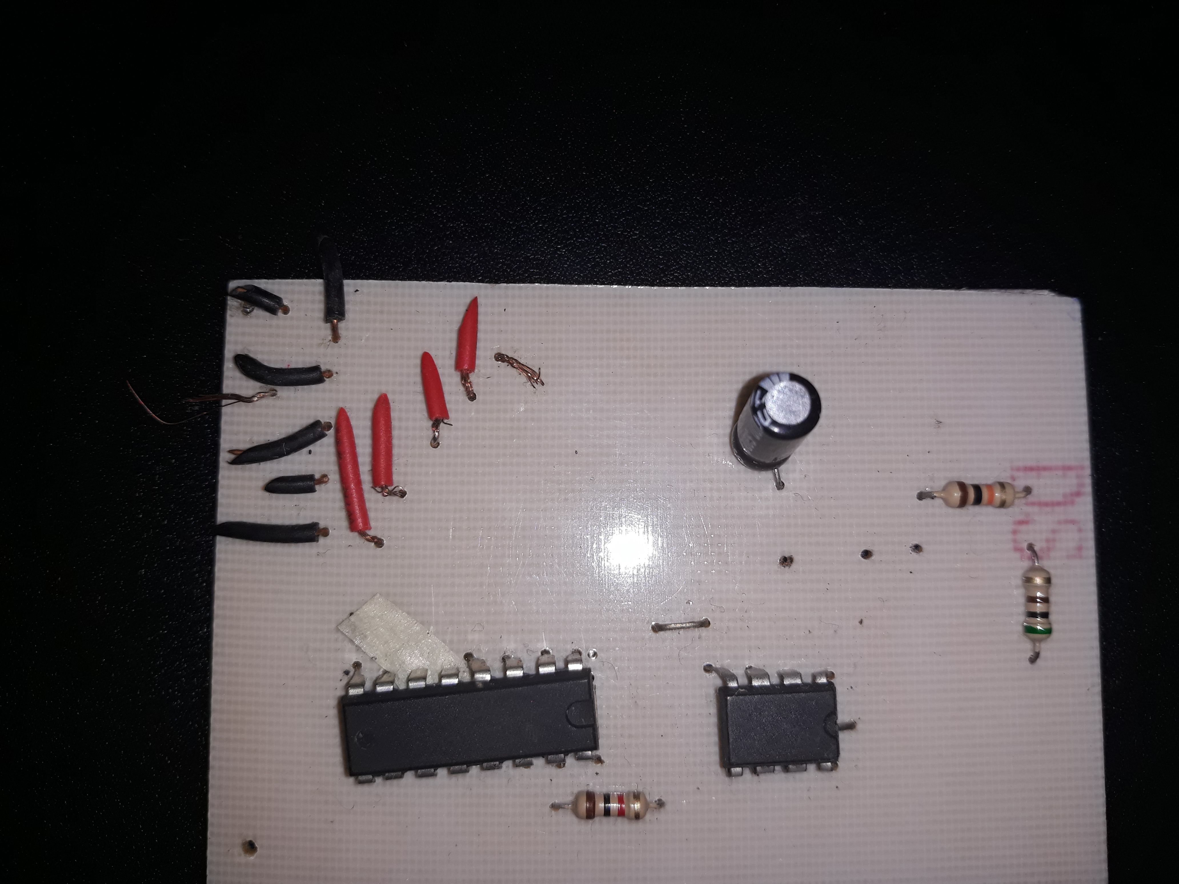
In this picture, you can only see the two (2) ICs because I separated the other one (1) since it takes up much space.
PCB SOLDERED SIDE

PARALLEL LEDs

Like I always said, Just be careful and avoid the leads or terminals of any components shorted because it can cause a minor to major damage.

The Running Lights Actual video
This project is not only limited as what the video shows us. It just wanna help everyone to make your own design depends upon on your creativity and desired uses.
Objective of this project
The main objective of this project is to learn how to design the schematic diagram of running lights circuit at the same time will teach and shows us how to used different softwares in testing components. This tutorial post will also helps everyone maximize their ability make a project better than this and hopefully apply this project in the future. This project is not limited to this application only , thus it depends on your creativity and desires for the innovations of our technology/technologies.
I hope that this will be helpful to everyone specially students and fan of Electronics ❤️
Yours sincerely,
@thinkvincent

Hi @thinkvincent after a long pause you are back here happy to
see you back in @steemit
thanks @maujmasti
yeah ehhehe. it's been a long paused. Nice to see you again bud ^_^
Hope you will now regularly post something here
Thanks mate