Getting a 12V radio to work in an old 6V car
A friend of mine is the proud owner of a '67 Citroën 2CV. This car, and I use the word loosely, has a 6V battery and won't support a modern radio that needs 12V. 6V cars are often converted to 12V, because it is more convenient, but he wanted to keep his 2CV original. The radio he picked was relatively low-power, about 10W. I doubted that would be enough to be heard over the engine noise at speed, but he chose it anyway.
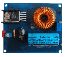
So, I designed a solution for him, a simple DC/DC converter. The circuit described here converts 6V to 12V at 1A sustained load current, giving 12W. I made sure it wouldn't die at 20W.
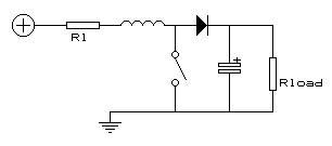
It works something like this:
When the switch is closed an extra current flows through the inductance and stores energy there. The capacitor supplies the load with current during this time.
After the switch opens the capacitor is charged by the energy stored in the inductance and an extra current starts flowing through the load, causing the output voltage to rise (energy is supplied directly from the input source also as long as the diode is forward biased). During this time, the system behaves like a RLC-circuit, so, after a while, the current decreases. The switch is then closed again and the cycle repeats. One could say that charge is pumped from input to output, increasing the output voltage up to the point where there is an equilibrium between the discharging of the capacitor while the switch is closed and the charging by the inductor while the switch is open.
The output voltage equals (ton / toff + 1) x Uin and is controlled by PWM of the switching action. For more information, see the Wikipedia article.
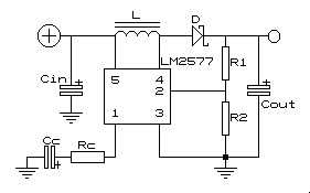
To implement this, I have used the LM2577T-ADJ from National Semiconductor, now Texas Instruments. It operates conform the given description and has a switching frequency that is well beyond audio frequencies. It is connected like this:
Parts list:
| IC | Switcher/regulator | LM2577T-ADJ (http://www.ti.com/product/lm2577) |
| R1 and R2 | Voltage devider for monitoring output voltage | 20Kohms pot. (Bourns) |
| Cin | Decoupling | 0.1μF, 63V MKS condensator (WIMA) |
| L | Use a good quality coil! | 160μH toroïd (2.5A, 70mohms, nickel-iron core) |
| D | Current higher than output current! | FR603 60V reverse breakdown, 3A Schottky-diode |
| Rc and Cc | Pole-zero compensation network | 2200ohms, 5% and 1μF, 63V elco (Philips) |
| Cout | Get a low ESR type! | 2200μF, 16V elco (Telecon) |
If you want to design a different DC/DC converter, you might want to take a look at Texas Instrument's site; they have a design tool there that can design your circuit for you.
I have no commercial or other ties with Texas Instruments
Photo and images are my own, from the same article on my website


Ah the buck converter :)
Yes. Well, boost converter, in this case.
Oh yea my bad, you're boosting from 6V to 12V :) Didn't think a car could be so old as to use 6V but then i re-read the post.
I don't think you have a good reason for flagging this post, @mazdakht2016.