What is a 3D printer? how is it done? - part 1 (I will share in 5 parts)
1. INTRODUCTION
The history of 3D printer technology dates back to the 1970s. In 1971, Piere Ciraud, a French scientist named, worked on a method of manufacturing by combining metal powders with the aid of radiation. In the same year, Wyn Kelly worked on a method similar to Swainson StereoLithography (SLA) technology where three-dimensional objects were produced by interlacing laser beams. In 1979, Ross Housholder reminded of Selective Laser Sintering (SLS) technology and worked on a production process in which three-dimensional objects were produced by solidifying the layer with laser beams from the raw material. Although these studies for 3D printing technology are not commercialized, in 1984 Charles Hull found a patent application for a machine that produces three-dimensional objects with SLA technology. Two years later, Hull, the accepted patent application, established 3D Systems Corporation in order to pass on the technology. Also in 1986, Carl Deckard found SLS technology and worked on a production device and method that combines the powdered raw material in layers by computer controlled laser. Deckard and his academic advisor, Joe Beaman Desktop Manufacturing (DTM) company established. Later, in 1989, Scott Crump invented FDM (Fused Deposition Modeling) technology and established Stratasys Ltd. Following these initial developments in 3D printers, successive advances were recorded in different 3D printing technologies [1]. 3D printer technologies have brought together many different technologies. These technologies are listed as fused deposition, laser sintering, polymer curing. Although it has widespread use and different design, the most commonly used technology has been the fused deposition modeling (FDM) technology. In this technique, a 3-D model is obtained by stacking objects in a 2-dimensional layer on a computer [2]
In this study, an FDM-type 3D printer was designed and manufactured, and then, using 3D filament, no mold was produced without need. Starting with an FDM software process on these devices, the software mathematically separated the STL format models into layers and sent them to a 3-axis Computer Numerical Control (CNC) controlled device to build these layers on top of each other. Thermoplastics materials were used in the study. These materials
The thermoset material was taken into the box compared to the material and the arduino was cooled using a brushless fan. In this way, long running print jobs prevent the card drivers in the arduino from getting warmed, and the life of the arduino is extended, and the decrease of the print quality resulting from the warming of the arduino is prevented. Performance bottlenecks were observed in existing 4-motor printers on the market, and a 5-engine i3 model was used in this study, taking printer performance into account prior to commissioning.
2.MATERIAL
2.1.Mechanical Materials
2.1.1.Rul financing
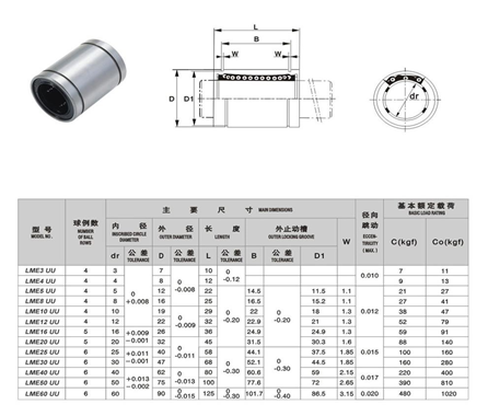
The basic task of the roller is to minimize the friction between two elements with relative rotational motion and to transfer the load smoothly [3]. Two types of bearings were used in this study. The LME8UU linear ball bearing is used for back and forth movement, while the 62th series fixed ball bearing is used for rotational movement .

2.1.2 Transmission Shaft
A ball-bearing nut is a machine element that translates the rotational motion into a linear motion by means of a spindle-mounted shaft . It has been used with purpose to move up and down the Z axis of the heater in operation.

2.1.3. Strap
A 5mm wide 1mm thread depth belt is used to move the table and heater in operation at regular intervals over the X and Y axes.
2.1.4. Pulley
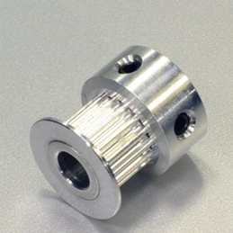
The power and motion of the moon, which rotates when the distance between the miller is long, is the machine element that transmits the miles that are rotated by one or more belts [5].
The drive is used to drive the belt with the drive it receives.

2.1.5. Kaplin
Intermediate element for transferring the rotational motion between the milling machine operating on the same axis [6] and used to provide the motor and gear milling connection during operation in the Z axis.

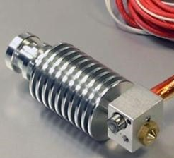
2.1.6. Nozzle
Heated by the heater and pointed out from the raw material.

Materials used ;
- Chassis ; ( 1 piece Aluminum chassis, 400x400x6mm )
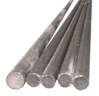
- Steel shaft ; ( 2 pieces Steel shaft Diameter, 8 mm - 320 mm & 2 pieces Steel shaft Diameter, 8mm-350mm & 2 pieces Steel shaft Diameter, 8mm-370mm )
- Screw shaft ; ( 2 pieces of threaded shaft, M5x300mm-2pcs & 2 pieces of threaded shaft, M10x380mm-2pcs & 4 pieces Vented shaft, M10x210mm-4pcs )
- Ball bearing ; ( 1 piece 625 quality ball bearing, Diameter 5x16x5mm-1pcs & 4 pieces 608 quality roller Diameter, 8x22x7mm-4pcs
- Pulley ; ( 2 Pieces Gt2 Belt pulley, Gt2 model number of teeth Z = 16 P = 2 mm & 1 piece Time belt, Tooth height = 2mm Length = 900mm & 1 piece Time belt, Tooth height = 2mm Length = 790mm )
- Screws , standards: TSE-TS61/5-13-6.8 ; ( M3x14-45 units & M3x24-3 pieces & M3x30-4 pieces, M3x60-2 pieces & M4x20-6 pieces & M8x30-1 & M8x20-1 pieces )
- bolts ; (standard : EN ISO 4032-6 ); ( M3-30 pieces & M4-6 pieces & M5x-2 units & M8-1 pieces & M10-34 pieces )
- 11 pieces LM 8 UU kalite , Çap 8x25mm-11adet
- GS11 kaplin , Diameter 8mm x32x40 2pcs
- Threaded Shaft , 5 pcs M3x8 mm
- Washer , standard - DIN 125 / A EN ISO 7089 ; ( & Diameter 3 Flat washer 60 pieces & Diameter 8 Flat washer 6 units & Diameter 10 Flat washer 34 pieces )
- Nut (standard - DIN 982 ISO 7040, M8 - Hex lock nut - 1 piece
- Cylindrical spring-Aadet (For Exstruder) Spring catalog see.
@orginalworks
You got a 6.73% upvote from @steembidbot courtesy of @josecca!
You got a 1.23% upvote from @allaz courtesy of @josecca!
Nice post👍🏼