The application of the symbol P&ID in the process of setting Temperature
The application of the symbol P&ID in the process of setting Temperature
This article discusses about the application symbols P & ID (Piping & Instrumentation Diagram) based on standard ISA (the International Society of Automation) in the process of setting the temperature to produce a controlled hot water.
Piping and Instrumentation Diagrams abbreviated P&ID is a series of schematic used in instrumentation and control activities/control/automation. In addition, the P&ID function for field technicians, engineers, and operators to understand the process works and how to know the concept of interconnect device instrumentation used.
Most industries have standards that his symbols is adapted to standard ISA S 5.1 Instrumentation Symbol Specification. Where such standards include some diagrams as follows:
-Piping & Instrumentation Drawing
-Process Instrumentation & Diagram
-Process Flow Diagram-PFD (a simplified version of P&ID)
The following step-by-step description of application symbol P&ID used at the temperature process.
The image below displays a pictorial diagrams simple yet informative.

Temperature chart from the above process can be concluded there is some device instrumentation used, namely:
-Steam as input.
-Pneumatic Control Valve as the actuator.
-Heat Exchanger, temperature transmitters, temperature sensing bulb and as sensors.
-Water as the primary medium of the process.
-Thermometer, Temperature Controller and recorder as a governing device/controller and monitoring/indicator.
From the picture above then elaborated into a few simple picture below that will be retrieved symbol P&ID as what worthy was applied.
Before the tag numbers and symbols.

The circle in the picture above as a place of tagging numbers P&ID like the picture below.

An Explanation Of The Tag.

X : Sign defines the components Process/instrument used (see table below).vHer example (the initial letter in bold):
Pressure, Level, Flow, Temperature.
Y : A sign that defines the function of the components of the ' X '. Her example (the initial letter in bold): Indicator, Controller, Recorder, Transmitter.
Z : Signs that identify a modification code ' X '. 123: the sign of the mean area code place of device instrument.
More details can be understood through the image below :

The symbol of the pipe and its connection (Piping and Connection Symbol)
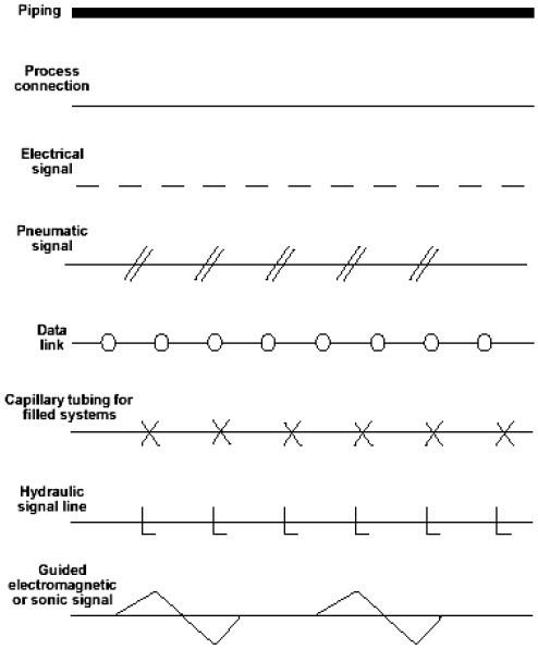
When developed again if displayed symbols such as pneumatic connection in addition to PLC as a signal, and also electrical data, then it can be made as shown in the picture below.

Thank you for reading this article may be useful
Source Engineering
About anime: @animesukidesu
About cars : @muhammadrovi
About nature : @riostarr