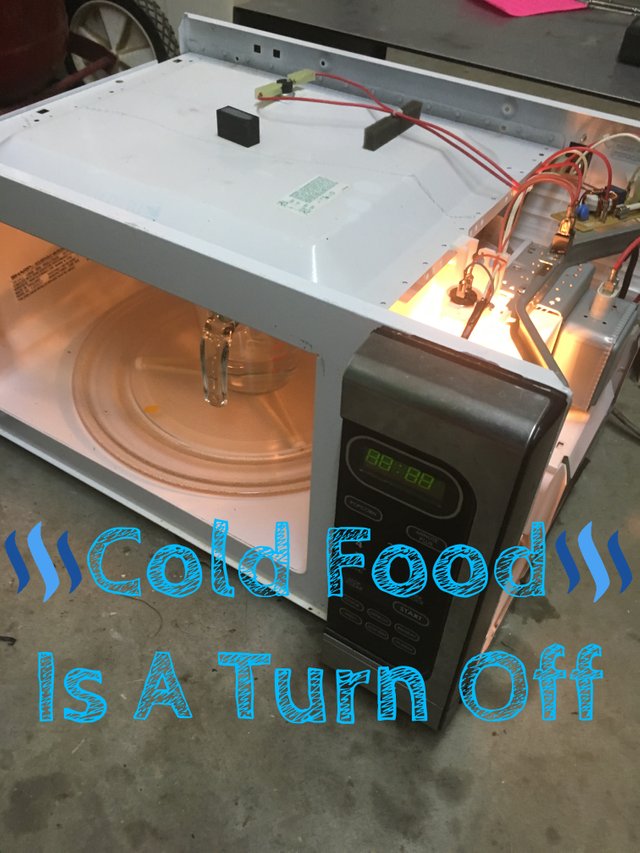
What's Poppin Everyone?
 It seems the Microwave Oven has become a larger staple at heating food than the conventional oven when it comes to ease of use and speed. Dont get me wrong, the quality of food produced between the two cant compare but if your on the run and need to nuke something up real quick you dont set the oven to 450, you set the Micro to 2 minutes. Over my lifetime I have been through several Microwaves and its common knowledge the higher wattage a microwave, the more powerful it is. More wattage also usually equates out to a higher dollar price.
My girlfriend @beckymeep recently had her Microwave stop heating food. I thought this odd as everything on it worked, food just didnt get hot no matter how much time you put it on for. I decided to take it apart and see if I could fix it. The Microwave was a Sharp Carousel Model - R408LS 1100 watt microwave.
I want to first inform everyone, @proteus-h wrote a wonderful article titled How to disassemble a microwave oven for electrical components to use in your DIY projects that may be a little old but is still relevant to this post and is very informative. Please stop by his blog and check it out!
DISCLAIMER! Microwave Ovens contain high voltage parts and severe injury or death can occur if the proper precautions are not taken. If you follow my instructions you do so at your own risk!
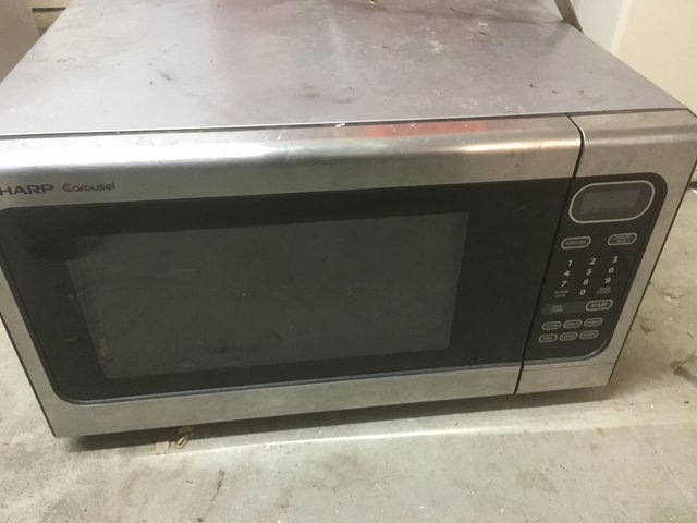
I started by removing the screws from the sheetmetal shell and continued to slide it off.
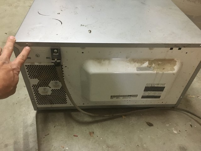
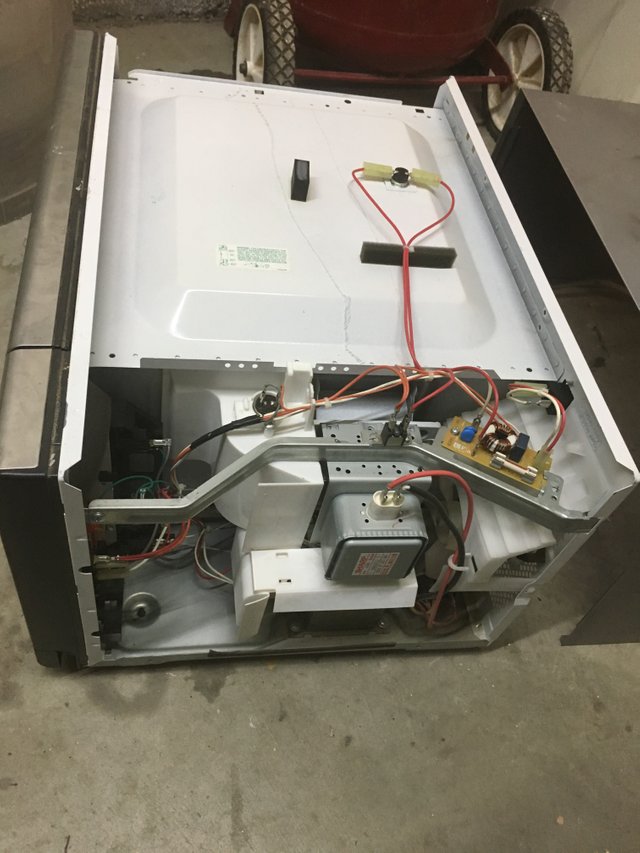
Once the sheetmetal shell slid off, the internal components of the microwave were in full view. Lets go through the various parts, what they do and how I tested them.
Before I do though let me show you the main issue, no heating. I took a cup of water and got an initial temperature with an infrared thermometer.
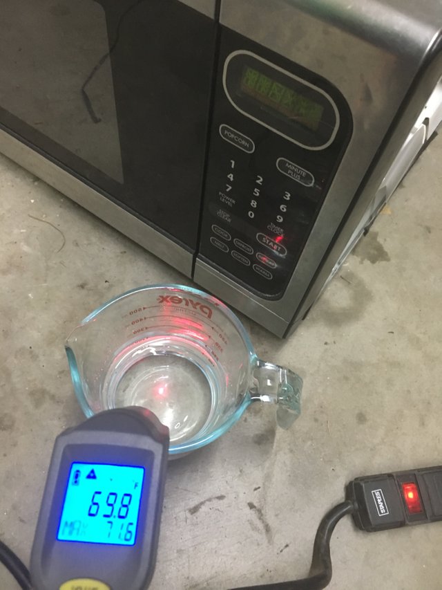
The room temperature water was then placed in the microwave on high for 1 minute and a second temperature was taken.
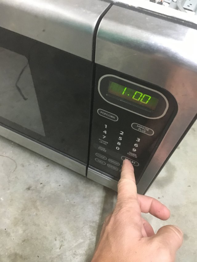
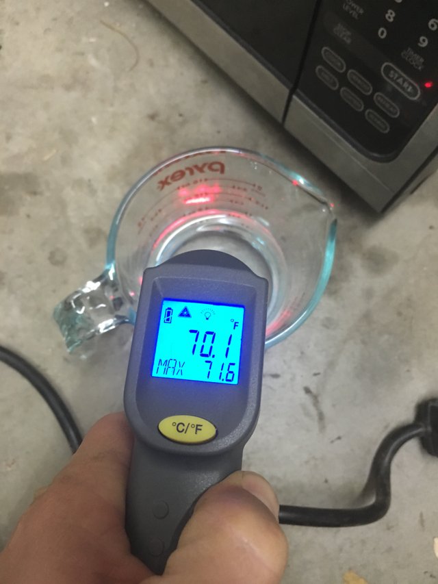
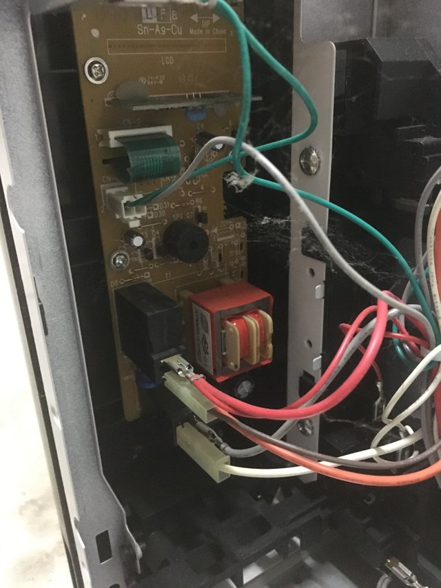
So no temperature change after a minute in the microwave. Lets get back to the various components and how to test them. I started with where the power came into the machine and worked from there. The machine was obviously turning on and running but I wanted to inspect everything and I will go over how to test working components for the sake of you the reader. You may have a different issue and can use this post as a guide. Where the power came in there was a small circuit board with a fuse, toroidal transformer, resister and a few blue capacitors. I have a theory, this circuit board is used to protect the vital low voltage components at the front of the machine from voltage spike. Any spike would blow the fuse and be absorbed by the transformer.
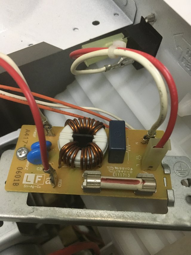
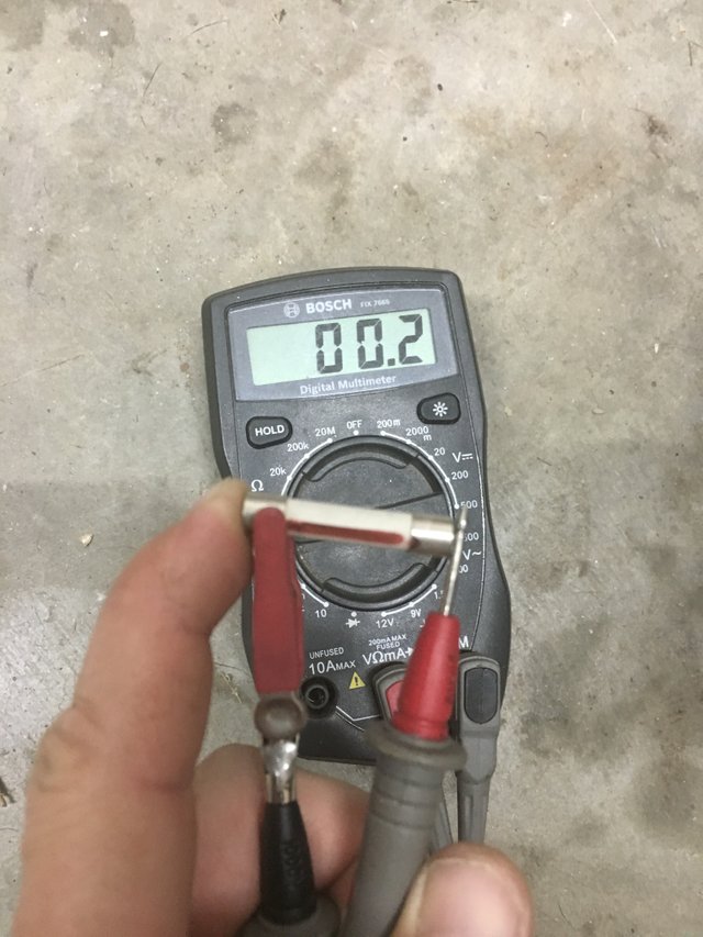
The fuse was colored and for the sake of testing, I tested it for continuity . On the 200 Ohm Setting it showed a complete circuit and a good fuse.
I opted out of testing the various switches for the door simply for the reason of brevity. If your microwave turns on but does not start when the door is shut, the switches that latch the door may be bad. Test them for continuity like above, while pressing the button. Make sure the circuit is complete, then broken when the button is either pressed or not (depending on what type of switch it is). As long an the circuit is interrupted through one of those actions, the switch is good. The low voltage transformer is in the picture in red.
From the front input board, the power then went on to the transformer. The transformer consisted of two input blades on one side. Two wires from the primary (white and black) and one wire (red) from the high voltage secondary windings resided opposite the input blades.

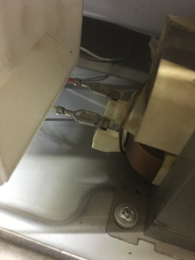

To test the transformer, test the resistance between terminals of the input, as well as between the two primary connections. Both readings came back good with less than an ohm of resistance with the multimeter set at its lowest resistance setting.
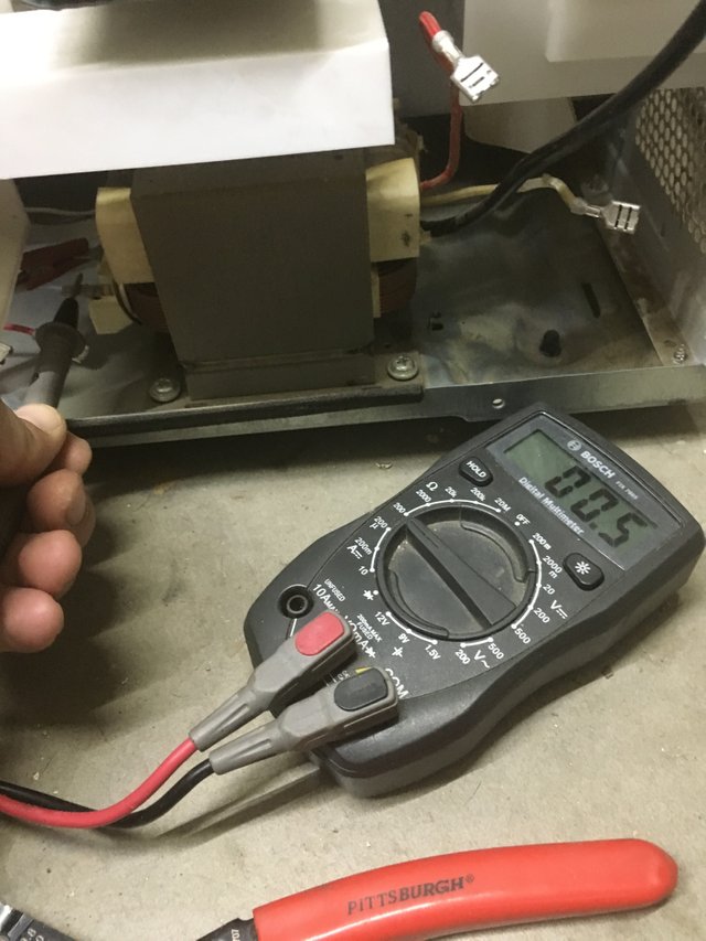
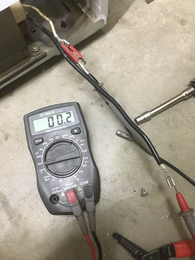
Aside from low resistance between the connections, each connection needed to be tested for shorts against the grounded out casing. If there is a short in the windings, the transformer will malfunction. I first had to find a spot on the case of the transformer that was bare metal.
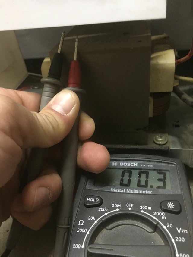
The multimeter was set to the highest ohms setting, and each component was tested against the case for a complete circuit. If a complete circuit was found, it would indicate a short.
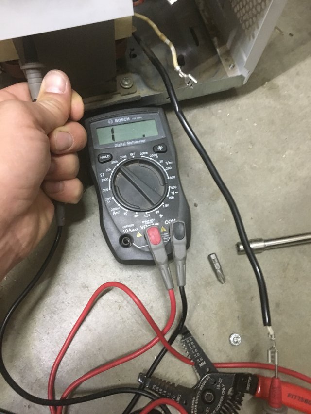
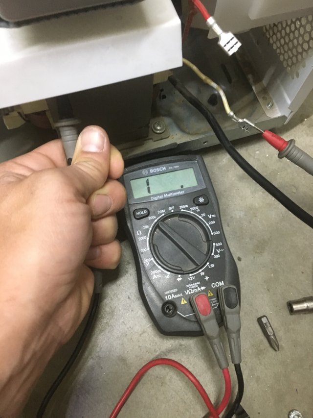
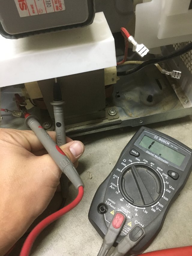
Everything checked out ok with no shorts to the case. Lastly, with the multimeter on the lowest ohms setting again, The high voltage secondary wire was tested against the case. Acceptable resistance values range from 50 ohms to 150 ohms depending on how powerful the microwave is. Mine rested within this value, although to me this seemed a bit high.
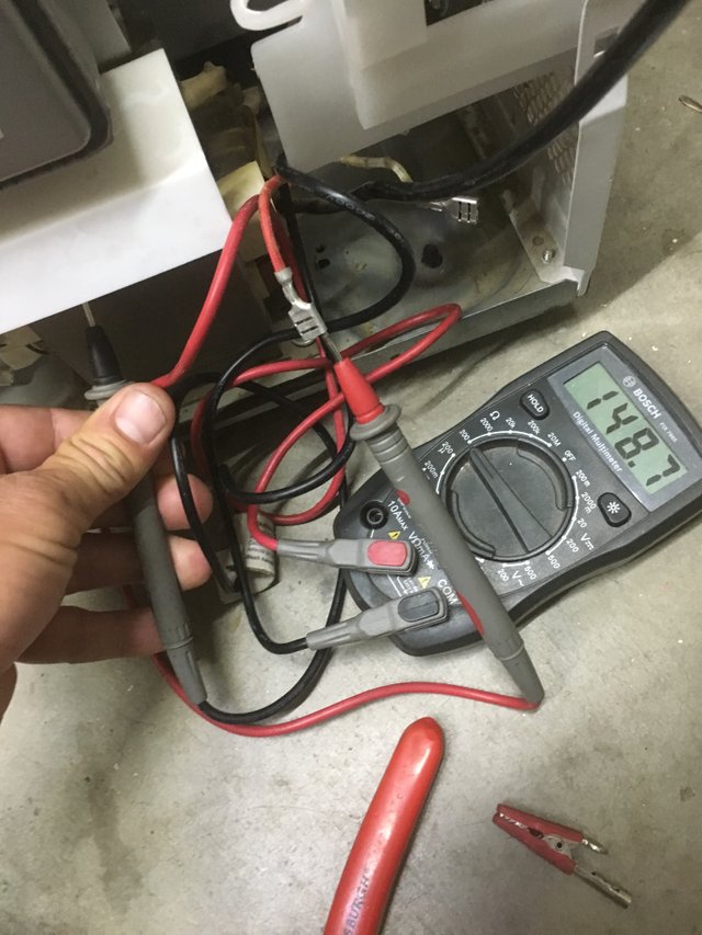
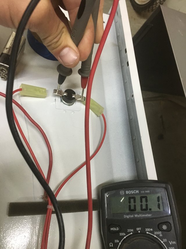
Before moving on to the the large capacitor. I quickly tested the oven thermal fuse for continuity to make sure it didn't blow. It tested out ok, and the fuse was still a complete circuit.
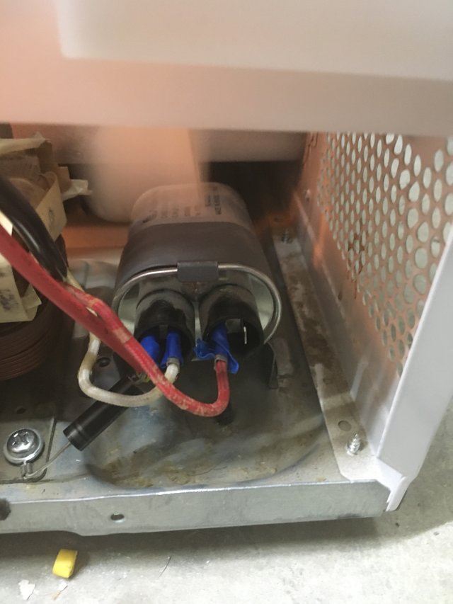
The capacitor was the next thing to test. This is where the high voltage is stored and before testing it I made sure to discharge the capacitor by using a screwdriver with a plastic handle and jumping the spade connectors to one another as well as grounding them out to the case. This step is very important!! The high voltage rectifier was then tested. These are often the problem when a no heat situation is encountered. I removed the capacitor with a socket wrench because I couldn't grab a screw driver well enough to remove the tight screw.
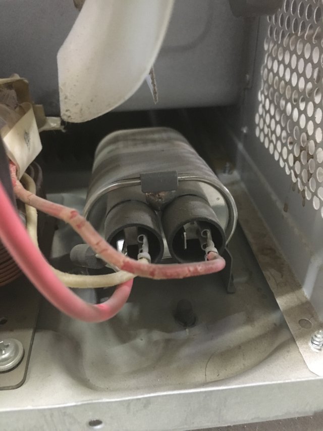
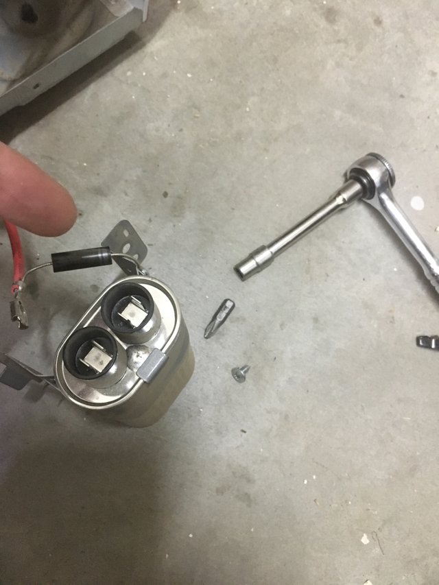
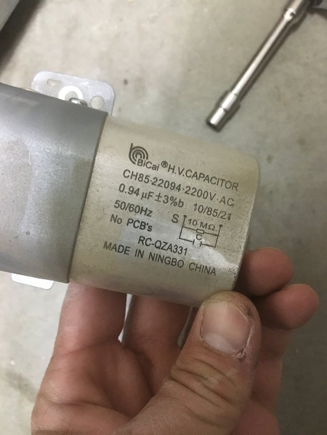
The capacitor in this microwave was rated at a whopping 2200 volts AC with a 10 mega ohm resistor built in.
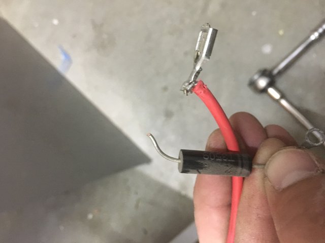
The high voltage rectifier was cut from the wire and unscrewed from the case. It needed to be separated from the wire to be tested. Later I would repair this by soldering it to the wire it came from and putting on a new female spade connector.
To test the rectifier, a 9 volt battery or any dc power source of at least 10 volts will do. Both the 9 volt batteries pictured were absolutely dead and no good to use so I dug up a Ryobi cordless battery rated at 18 volts.
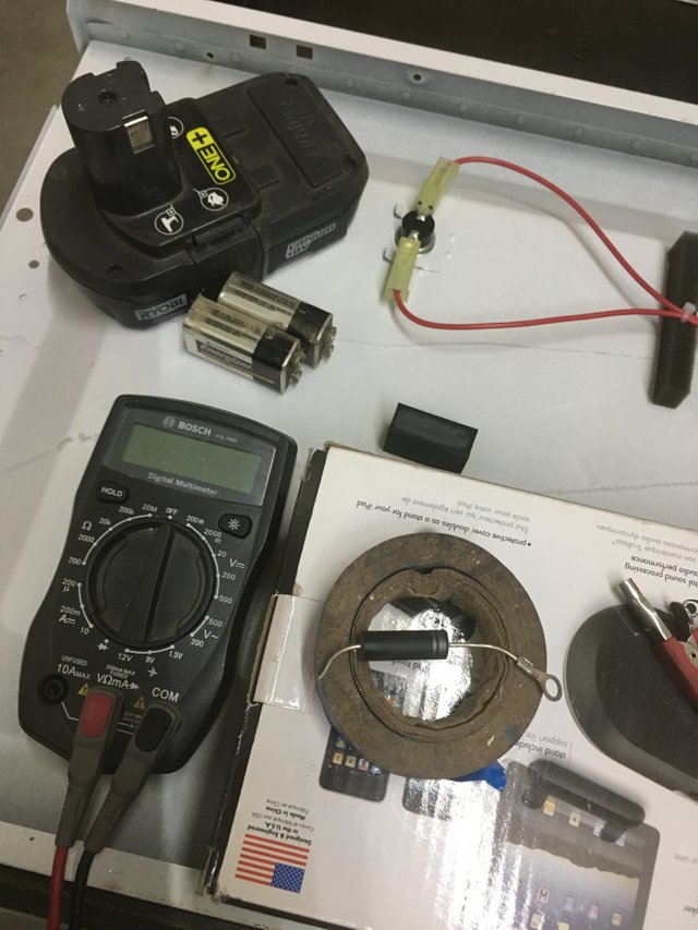
The initial voltage on the battery was 20.3 volts.
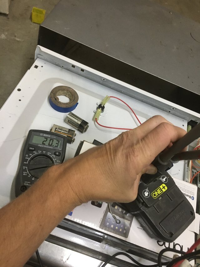
I then set up the rectifier in this manner: The positive side of the battery would be probed by the black (COM) wire on the multimeter. The red side of the multimeter would be attached to the side of the rectifier that was cut from the wire. From the opposite side that was grounded to the case, a jumper wire was used to complete the circuit to the negative side of the battery. Alligator clips help in this situation but I only had one to use. With the circuit complete, the voltage was now 17 volts DC, and showing that at least the rectifier was working in that setup. Expect a 3 volt drop across the rectifier; if no drop is noticed, the rectifier is faulty.
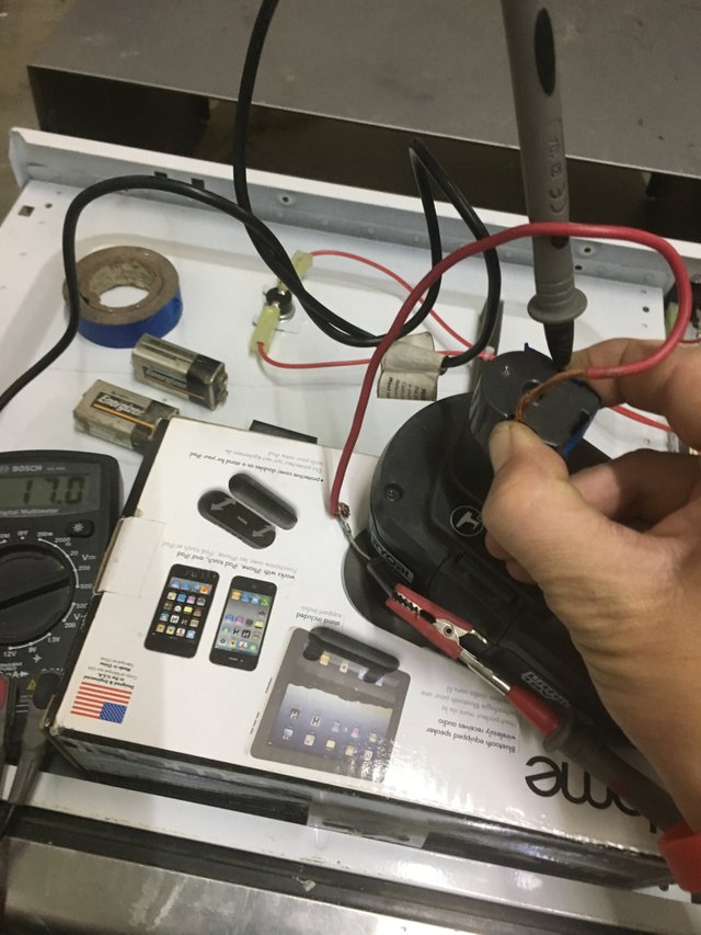
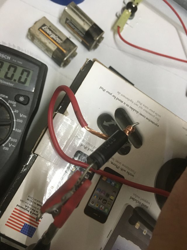
Now to conduct the second test, simply reverse the wires at either the battery or the rectifier. I chose the harder way and reversed them at the rectifier by attaching the red probe from the multimeter to the side of the rectifier that was grounded and the jumper wire to the cut side. Either way will produce the same results and those should be NO VOLTAGE. If voltage is read on the multimeter, then the rectifier is faulty and needs to be replaced. The rectifier must pass both of the tests above to be considered good.
A little frustrated with the rectifier being good and still in the same situation that I started, I moved on to testing the capacitor. With the ohm meter set to the highest Ohm setting I probed both the outer spade connections. When conducting this test, the meter should ramp up to 10 mega ohms of resistance, if not the capacitor is bad.
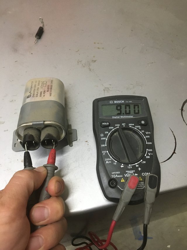
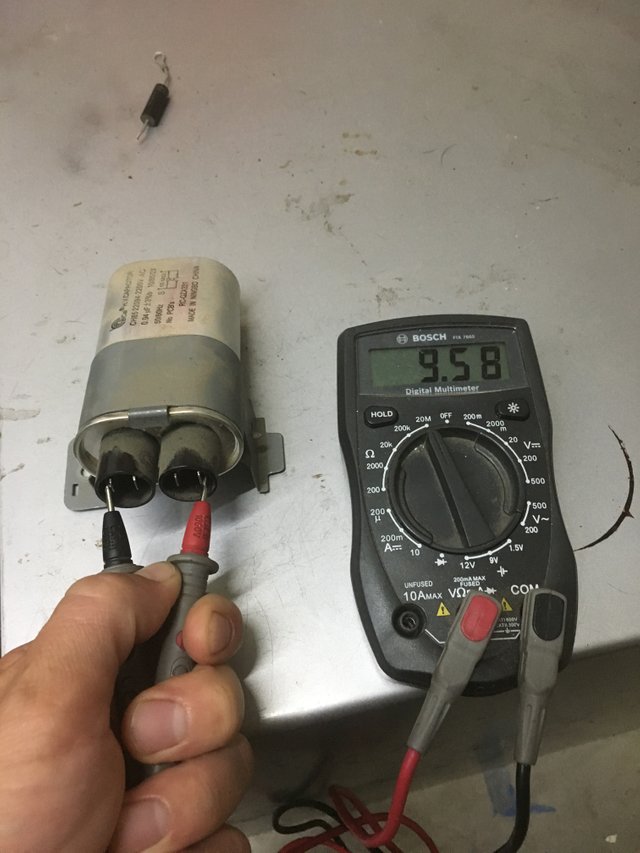
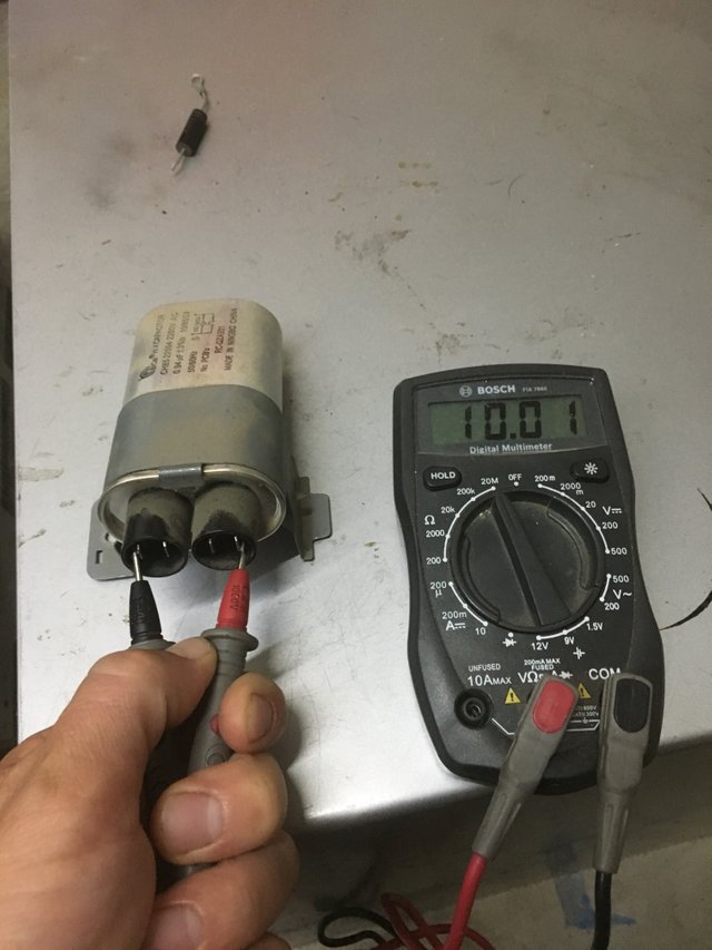
The capacitor passed that test so I then moved on to testing each spade connector with the ground of the body of the capacitor. There should be no continuity on any of the spade connections or a short exists inside the capacitor.
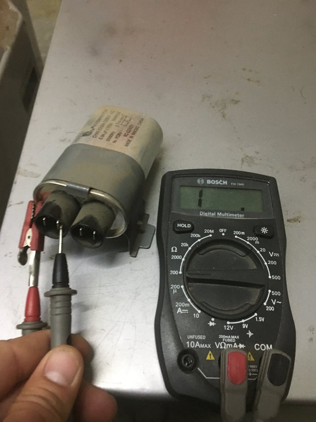
This was getting frustrating as now the capacitor had completely tested functional. Was it the Magnetron? I was hopeing not because I was sure that would be the most expensive part to buy. I checked the resistance between the connections on the lowest ohm setting and everything seemed good.
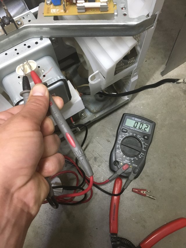
Then like the capacitor and transformer, I tested for shorts between the spade connectors and the case ground. No continuity was found so the Magnetron seemed ok.
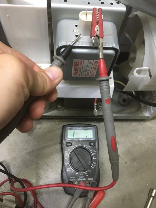
Next to the Magnetron was the cooling fan. I figured I would include it as the shinny transformer that is next to it catches the eye. It worked fine so I didn't test it.
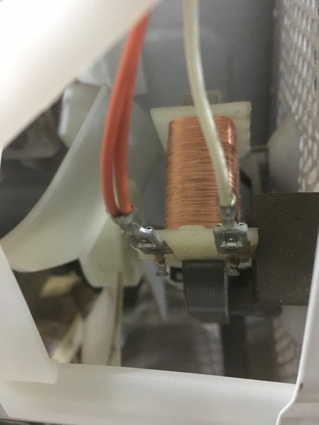
With little hope I even went so far as to plug it in and make sure the transformer was getting voltage
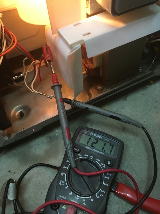
Soooo......WHAT WAS WRONG WITH IT??????? Everything tested ok so far and could not account for the lack of heating. I was about to call this thing parts but before then I plugged everything back in and decided to give it one more try. I soldered back on the rectifier and screwed everything back down. One thing came to me as I was plugging everything back in and that was the red high voltage secondary wire was plugged into the outermost spade connector but the connector next to it was not used (refer to picture of capacitor way above). The two other connectors on the capacitor were taken by the primary windings, so what went to this unused connection??? I decided to swap the high voltage secondary to the unused terminal and buttoned everything back up.
I tested the temp of the water and it was roughly the same as before. I failed to get a before picture of the temperature for this test. I set the timer to one minute and proceed on.
After the minute I tested the temp again and to my surprise IT WORKED!!! WHAT THE? A steaming hot cup of water!
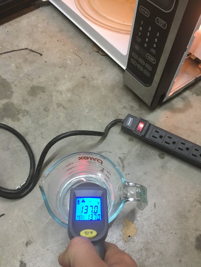
WOW! By simply swapping the connection of the high voltage secondary to that unused terminal the microwave was now in fully working order. This was crazy because everything tested out ok. I slapped the shell on and @beckymeep couldn't be happier to have her powerful microwave back up and running and not have to worry about buying another one.
I hope this post helps you diagnose any problems you may have with this everyday household device. Thank you for taking the time to read it and take care everyone!
 All photos, unless otherwise stated or sourced, were taken by @csusbgeochem1 and may not be reused without permission. Animations and cover photo created by @csusbgeochem1 using GIMP.
If you found this story interesting you can find more like it by following @socalsteemit and help us expand the Steemit community together

Join the SoCal Steemit Discord group today and meet others around you


This is so descriptive article. I appreciate your efforts. I had once got a chance to open my 1.5 t air conditioner due to low cooling. I suppose the principle of AC is similar to micro wave. The problem was located as the bad high voltage capacitor(10 uF/450 V, ), which I could replace myself with due precautions as described by you. That was a lot of learning though.
It is a bit much to take in, I just felt it would be incomplete if some of the tests were missing. Yes, AC systems have similar capacitors that can go bad. They get pretty pricey. Thanks for the Comment!
Can't stress this enough - it's not just @csubgeochem1 covering their ass. There are components which can kill you in these. IF you know what you're doing, it's relatively safe, but don't just go digging around in them.
Right on @effofex! Ill be honest I was careless in a few of these steps. Thanks for backing me up!
Hi csusbgeochem1,
LEARN MORE: Join Curie on Discord chat and check the pinned notes (pushpin icon, upper right) for Curie Whitepaper, FAQ and most recent guidelines.
AWESOME! Im VERY appreciative! I strive to bring the best content possible to this platform. Thank you to everyone at the @curie team!
The content of your post is very interesting, I really admire it ..
And I always support your success