Why building yet another 3D Printer ? (Part 4)
Preassembly and prototyping time for the XY Gantry !
Finally, I received all the main parts, it is time to perform a preassembly to check what are the issues, what is missing, and I started prototyping of some parts.
Chassis
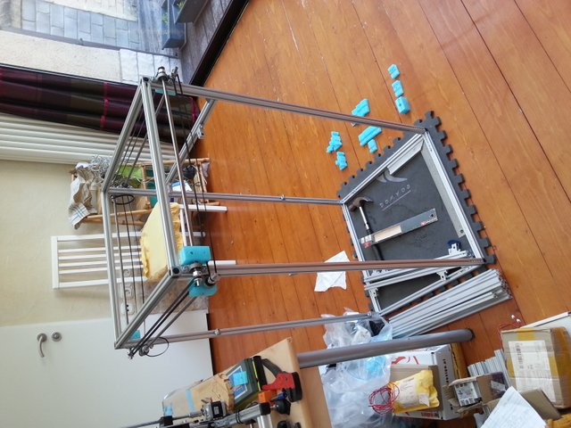
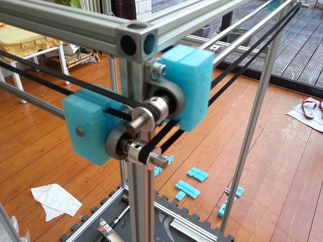
I made a few changes with respect to the original idea on the CAD, I am using some square connectors at the 4 corners. It increases a bit the height and the width of the assembly. This is not a small thing as you can see on the photo. Next time I will pay to avoid to tap by hand (too much time for a sketchy work). It is just a preassembly for fitting, additional brackets and additional beams are mandatory for the rigidity.
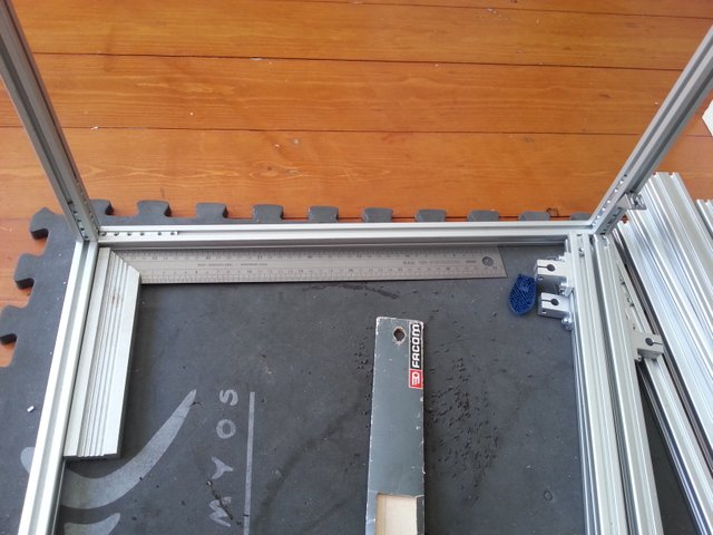
Follows another photo to give you the scale
The height is now 1040mm, the length and the width of the frame are 540mm (all 8mm hardened steel rods are 600mm).
XY Gantry
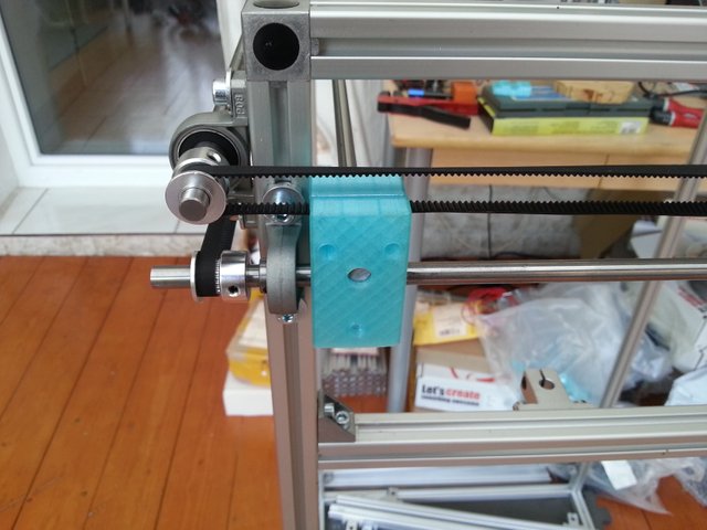
I started the assembly of my external XY Gantry.
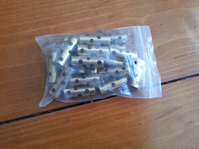
I am using exclusively Brass Bearing as follows (Ultimaker 2 common parts)
On the following photos, you can see in more details the assembly
Prototyping process
I am using PETG because it is stronger than ABS, PLA, relatively easy to print with, it does not stink, it is also flexible and it has good impact resistance, however it shatters but it is a nice property if you use it properly for supports (easier to remove). It has a transition temperature of about 70°C, probably I can use it for the part to hold the hotend.
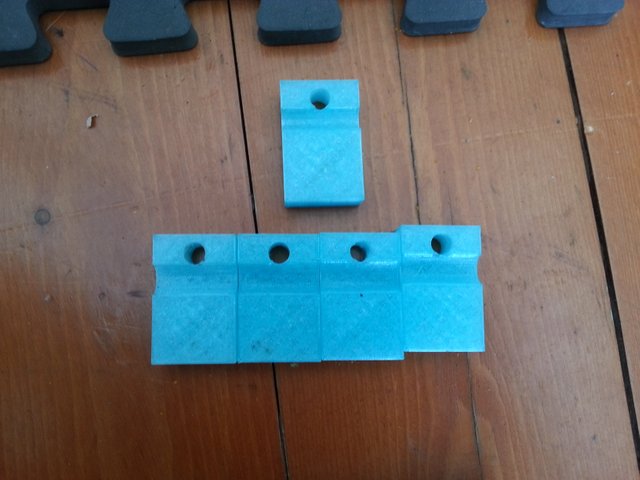
I started by building the following small parts to have a rough idea of the belt paths and other issues.
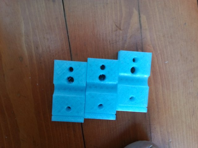
Then, I built the following one integrating the belt holder and 2 screws, however having a symmetric part is a bad idea due to the belt center that should be passing through the perpendicular plane passing by the center of the rod. Also, I learned I need to add in the design a gap to adjust the tolerance with the belt that sits into.
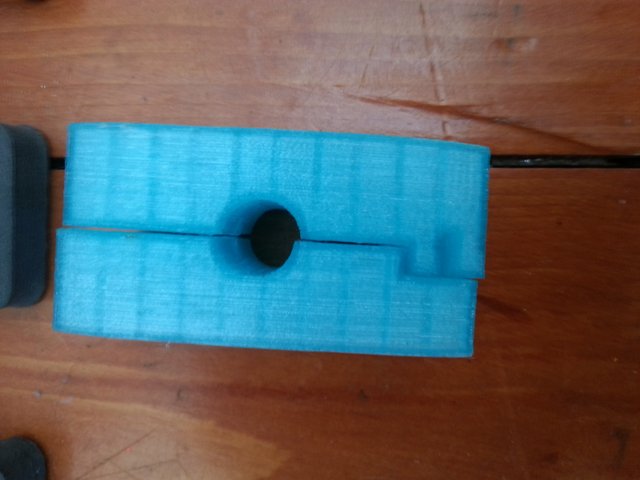
Now, this one contains both asymmetric parts for one of the X or Y dimension.
You can see the offset used for the belt holder.
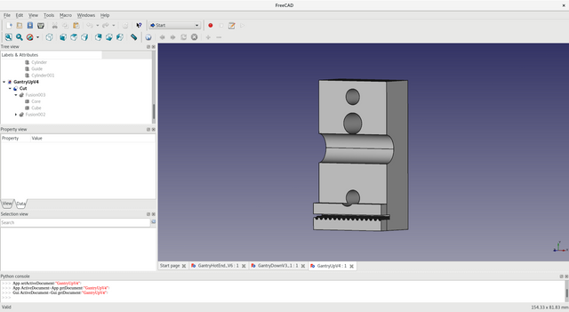
Screenshot of the part in the CAD.
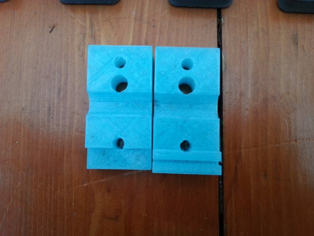
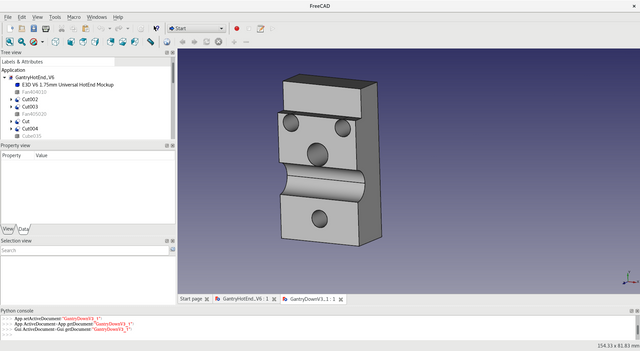
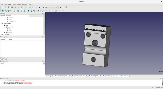
The other axis is just having the belt path on the top. The idea is the same, just a few differences on the distances and where are the holes to fix it.
Screenshots of the parts in the CAD.
In the next part I will talk about the prototyping design for the hotend support on the gantry (still working on it)
very curious what you are going to 3d design and print :-). Good luck with building your 3d printer.
Thank you ! I have already a few requests from my wife to build big things :-). I am not a 3d designer, if you have interesting parts, I will be glad to try out.
Most of my time is devoted to finish my slicer for 3d printers. I put a few resulting prints if you are interested here https://twitter.com/chopchop3d and there https://www.thingiverse.com/boucaron/makes/page:1 (I am using a cheap printer, it is easier to stop slicing issues on those)