Design, Fabrication and Testing of the Suspension Subsystem of a Single Seater Off-Road Buggy
The overall purpose of a suspension system is to absorb impacts from course irregularities, such as bumps, and distribute that force with the least amount of discomfort to the driver; without compromising on the agility of the vehicle. The suspension not only dictates the path of the relative motion but also controls forces transmitted by sprung and un-sprung mass.

Parameters determination for designing:
The designing parameters related to each part were determined separately for each part. For the design of the A-arms the minimum length of it was determined on the basis of the formula:

Where Ymin is the linear displacement of the ball joint, Zmin is the lift of upper arm, Rmin is the length of the A-arm and ‘a’ is the distance between ball joint and the inboard point. Rmin= 344.3 mm and so Rmin was taken as the base value for the length of the A-arm and then the actual lengths were determined by the variation of camber angle required according to the travel of the wheels.
The stiffness of the Shocks was determined using the formula:

The shock was designed for a load capacity of 1800N which thrice the force that acts on a single front suspension subunit. The rear suspension coil was kept at three times stiffer than that of the front as the rear carries the engine and so is the heavier side of the vehicle. The front coil stiffness is 22.11N/mm while rear coil stiffness is at 66.67N/mm.
Positive camber angle was selected so as to increase the load capacity of the buggy while the negative caster increased the agility of the buggy.
Design Specifications:

Front suspension assembly and Rear suspension assembly
The Front suspension specifications are as follows:
Type of suspension: Double Wishbone with unequal A-arms
Material used: AISI 1018 1”x3mm for both upper and lower A-arms
Length of upper A-arm: 370mm
** Length of lower A-arm: 380mm
** Caster: -4 degrees
Camber: 3 degrees
Shocks: Custom made shocks with 15inches eye to eye length and 1.5inch pitch.
The specifications for Rear suspension are as follows:
Type of suspension: Semi Trailing arm (single control arm) suspension with integral upright.
Material used: Flame hardened carbon steel swing arms
Length: 558.8mm
Camber: 0 degrees (fixed)
Shocks: King’s custom made shocks-12inch travel with 29inch eye to eye length and 2inch
bore.
Testing of the suspension:
The setup which was installed for testing, the prototype include the following components mounted at different critical points on the vehicle: one ADXL 330 accelerometer was installed on the lower a-arm near the ball joint on the front left as well as right sides. Similarly one ADXL 335 accelerometer each was positioned on the rear right as well as left uprights. Also, one ADXL 330 accelerometer was mounted below the driver, close to the C.G of the vehicle. The total of 5 sensors, each measuring readings of acceleration on 3 axis (X, Y and Z) transmitted their readings to 3 National Instruments USB 6009 Data Acquisition systems as voltage variations with a sensitivity of 0.3volt/g via single strand wiring. The 3 DAQs were then linked to a Laptop computer which served as a data collection and manipulation unit. Above figure shows the data flow sequence for the test set-up and second figure shows how the DAQs are mounted onto the buggy. The test was carried on a “triple bump” terrain profile with approximate height of 5 inches and patch length of 60 inches made out in tarmac surface.

Data Flow Sequence
.png)
DAQs wired and mounted onto the prototype
Results:
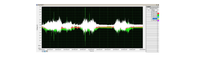
The readings were recorded after terrain testing in the form of voltage v/s time graph. The voltage can be converted to acceleration by multiplying a constant that is unique to the particular group of accelerometers. The maximum and minimum values of the accelerations are tabulated and compared.
Figures below are showing the acceleration input patterns through the wheels into the system.
Voltage v/s time for Front left suspension
Voltage v/s time for Front right suspension

Voltage v/s time for Rear left suspension

Voltage v/s time for Rear right suspension

Voltage v/s time for CG sensor

Table: Maximum and Minimum acceleration values at the accelerometer
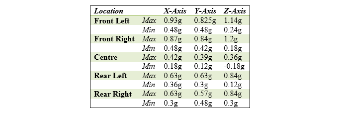
Above table shows the maximum and minimum values that were recorded from each accelerometer located at the critical points of the vehicle. The actual readings which were in volts were converted in terms of acceleration due to gravity (g) by multiplying it with a constant, 0.3 volt/g.
Conclusion
- A considerable reduction in the acceleration values were recorded at the C.G and these were contrasted against those at the other four wheels. This indicates a significant damping of the terrain excitation forces.
- Onboard excitation sources, predominantly the engine vibrations have added noise to the data collected. This could be eliminated by using improved vibration isolation systems.
- The study also features future prospects for Fast Fourier Transform of data so as to eliminate unwanted noise in the data thereby refining the readings obtained.
- Also the vehicle could be tested for different values of damping, as we are using a semi-active suspension system, at various vehicle speeds.
May I suggest citing the sources for parts of the content and images, so that post can be verified to be original post. Thank you. Great Work.
https://www.researchgate.net/publication/280384921_Design_Fabrication_and_Testing_of_the_Suspension_Subsystem_of_a_Single_Seater_Off-Road_Buggy
@originalworks
The @OriginalWorks bot has determined this post by @afzal-anees to be original material and upvoted(1.5%) it!
To call @OriginalWorks, simply reply to any post with @originalworks or !originalworks in your message!
Thank you very much for me. Thank you so much for sharing this post with us
My pleasure😎 keep following for more genuine contents.
Thanks to me, important things have been explained to me
Hi, i have seen taht you deposit sbd in hitbtc, did you sbd reflect in wallet in hitbtc?
Not yet
Now this is the kind of trial and error I can get behind.
Yes just a trial for once...!!
And shittt wth I have done..
Hah to you it's shit, for me it's rather impressive.
Thankyou my friend I am glad glad you liked it, I work hard on every post and when I got such good friends like you then I am extremely happy...
Keep on tinkering buddy!