Isometric Drafting- An Easy Presentation of How Technical Drawings Should be Made
Technical Drawings, the way or the actual plan for making a product or a simple project.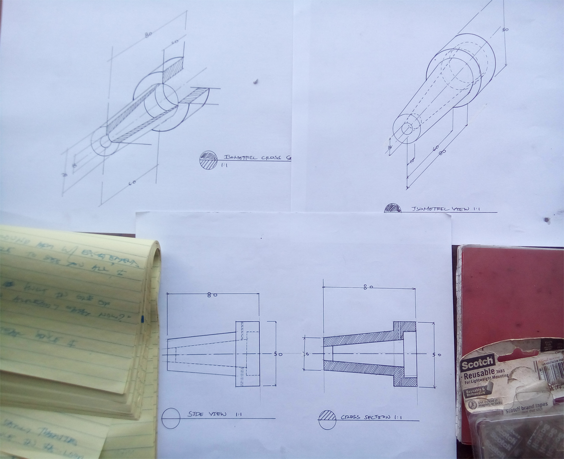
Technical Drawings are often used in factories that does mass production or just per order products(only small quantity orders). Without these drawings, the said product will be an impossible job for the one who will make the product itself.

Today, I'll show you guys the basics of doing a technical drawing by presenting this step by step process of the drawing I made of a hole piece for a pressure shaft that I designed years ago when I was still working for a metal production company. It's an easy and rewarding activity, hope you try it.
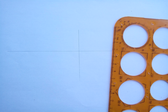
For this activity, you will be needing a pencil, a circle template(the orange ruler above), a pencil, some technical pens and a compass.
Mix Your Blood with the Ink You Use, You Draw to Live, not to Brag
That line above that I used as a section title is my most favorite line from my favorite comic book titled Bakuman. Just wanted to share because it sounds cool.
First thing to do is draw an intersection. This lines will be the center line and the starting line for the hole piece.
 ]
]
Start drawing the piece with the measurements in mind, for this one I draw the lip part in 20mm.

Then drop the neck. Just imagine how it goes like in the picture in the introduction.
Since there will be a taper, this method will be needed. Draw a measured line from the center line like shown below, the measure of that part is 20mm in diameter, with that, just count 10mm from each side of the center line and draw a line like what is shown below
Then mark the other end of the circle which is 35mm and connect the dots with a line to form a taper. See? Its easy.
Add the other details like the hidden parts.
Here, I added two small holes on the lip part. This holes will be the exhaust holes or the air escape. This parts will release the air when the shaft gets inside the hole. This holes are very critical since the measurements of these shaft and hole has a really critical tolerance of 0.010mm-0.001 that makes air almost impossible to escape once trapped in those parts.
note: tolerance is the margin of sizes allowed in a piece, this term is used in high precision measurements
I made the same drawing for the cross section drawing. That cross section part is really interesting so keep on reading.

Inking
First ink the center line in broken lines in this manner. This is the official way of drawing center lines so pay attention to it!
Draw the the revealed parts in solid lines.
Finish the revealed parts.
Then draw the hiddne parts with broken lines like this.
Finish it.
Add measurements.
Now, here is the cross section part(side view). When you do a cross section part, imagine that the piece was cut into half or a quarter of it has been removed. At this case, I cut it in half.
Draw the revealed parts in solid lines like what I did earlier in the first drawing.
Since we did cut the piece in half, the hidden parts in the first drawing are now revealed which should now be drawn with solid lines.
FInish it. Next comes the fun part.
Draw diagonal lines across the sliced part.
For satisfaction, I took pictures of the whole process of making these sliced part.
So beautiful.
There, the lines are now done.
Put measurements and dimension lines
There we're done for the side views, now lets go to the more exciting part, the isometric drawings.
For this part, you will be needing a compass beacuse there will be diameters that the common template doesnt't have.
Draw the center line.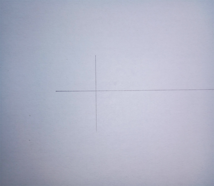
Draw a 45 degree line from the center line of one of the diameters. This 45 degree line will als be a center line but a Z-axis center line.
Draw another set of center lines in the end of the Z-axis center line.
Now set your compass to 25mm to draw a 50mm circle.
There, perfect!
Draw the smaller lines with the circle template.
Start drawing the piece in shape.
See the other 50mm diameter circle there? That will be the end of the lip part. To draw that, measure 20mm from the first circles center line across the Z-axis center line and draw another center line, then draw the 50mm diameter circle. See it? From ehre, you should already be able to imagine or understand the things that will be going on in the next pictures.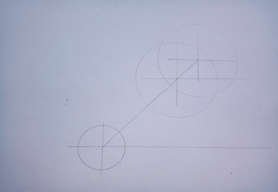
See? Just use your omagination when doing this.
Just connect the circle ends for the taper. Neat huh?
Now with inking, draw the Z-axis center line as the actual center line for the whole hole piece.
Assemble it, if you fail in your first time, try it again. It might be tricky at start since you might be needing some imagination excercise to be able to do slightly complicated drawings like this with several parts.
Here, I inked the big diameters with my compass with a technical pen add on.
Seriously, I just want to show my cool compass and technical pen here.

Draw the hidden parts in broken lines like in the first drawing.

Finish it.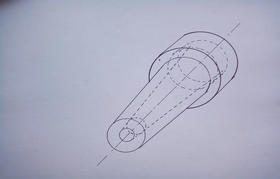
Add label and measurements.
Now the isometric cross section.
Same thing with the first isometric drawing but this time we will draw the slice line from one end like this.
This cross section drawing is presented with a quarter cut.
Draw the first diameter but only in three forths.
Start putting in the details.
It already looks nice in this part.
Add more details with adding more solid lines.
There, now emphasize the sliced area.
:D
Done!
Add label and measurements.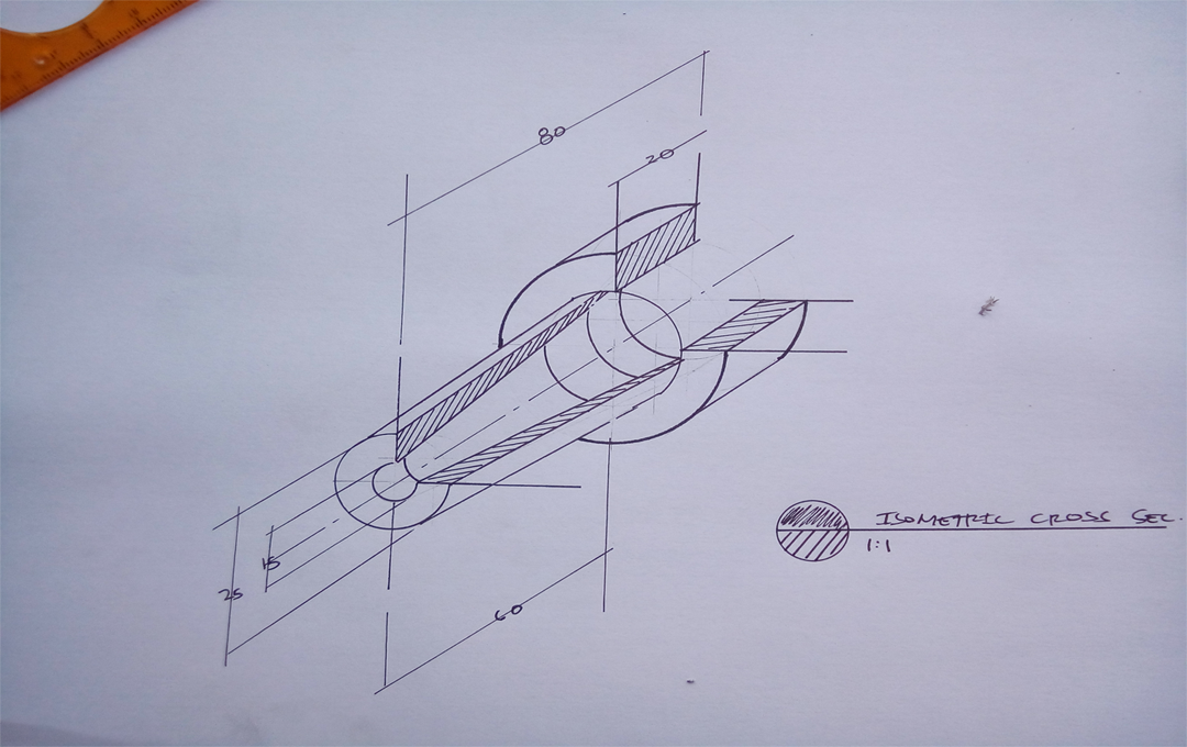
And there you have it! i forgot to add the *exhaust holes here, haha. If you really paid attention in this post, you should be able to do those holes with your own.

Anyway, for yesterdays post, I just realized that I did two false claims there. First is, the breakfast nook is located in a close area. A breakfast nook is a dining room that is designed to cater small number of people. Second is, it is not exactly correct to say that westerners design their houses with the first thing that you will see is the kitchen. They design their houses with an easy access in the kitchen right from the entrance that is usually aligned with a stair. For more reference in this detail, just check out the cartoon titled Rick and Morty, Rick and Morty's house is a good example of this design I'm saying here.
Thank you for dropping by, have a nice day!
A lot of typos hahaha
Hahaha, the typos
Good to see you having a successful post this time, that other post you did was good too. The floor plan thing. I cant do those kind of drawings hehehe. It requires some brain.
Congratulations @peterpat! You have completed some achievement on Steemit and have been rewarded with new badge(s) :
Click on any badge to view your own Board of Honor on SteemitBoard.
For more information about SteemitBoard, click here
If you no longer want to receive notifications, reply to this comment with the word
STOPCongratulations @peterpat! You received a personal award!
You can view your badges on your Steem Board and compare to others on the Steem Ranking
Vote for @Steemitboard as a witness to get one more award and increased upvotes!