Voltage Transformer basics and it's working principle
A transformer is a static device which helps in electric power transformation from one circuit to another without modifying its frequency. The voltage can be increased or decreased in the circuit which also results to proportional increase or decrease in the current rating. Here, we will be discussing transformer basics and working principle.

Transformer
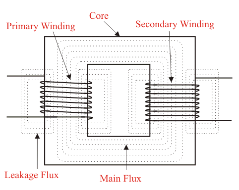
The main principle of transformer operation is common inductance between two circuits joined together by common magnetic flux. A transformer consists basically of two coils that are electrical and inductive, but are magnetically linked through a path of reluctance .This principle is based on faraday's law of electromagnetic induction which states that the EMF( electromotive force) of a coil is directly proportional to the rate of change of magnetic flux with respect to time.
Working Principle of Transformer
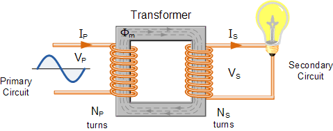
A transformer of single phase consists of two electrical coil of wire in which one is termed “primary winding” and the other “secondary winding” . The primary side of the transformer is defined as side that collects the power while the secondary side delivers power. The primary side usually possesses higher voltage in single phase transformer.

Single phased transformer
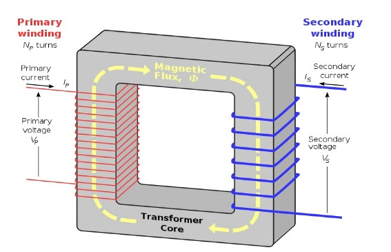
These two coils are wrapped together around a core (a common closed magnet iron circuit) but are not electrically in contact with each other. The soft iron core isn’t solid but composed of individual laminations connected together to assist decrease core’s losses.
The primary and secondary coils are magnetically in contact through a common core which allows transfer of electric power from one coil to another but the two coils are not electrically in contact. When the primary winding is being connected to an electric source, a magnetic field being developed passes voltage into the secondary winding.

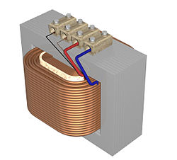
Transformer construction
In summary, for the two coils winding in the transformer, there is no direct electrical connection. The primary winding transforms the electrical power into magnet field when connected to the input voltage supply while secondary winding transforms alternating magnetic field into electrical power of required output.
There are two types of transformers which are; step up and step down transformer. A step up transformer is used to increase the voltage of secondary winding in preference of primary winding while a step down transformer is used to decrease the voltage of secondary winding in preference of primary winding. The third type of transformer is impedance Transformer. This transformer produces the same voltage on its secondary winding as its primary winding.
Difference between the number of coil turns on the primary winding (Np) and number of coil turns on secondary winding (Ns) accounts for difference in voltage between the primary and secondary winding.

Transformer core winding
A ratio called a ratio of transformation is the ratio of number of turns of primary coil to the ratio of turns of secondary coil. It is commonly known as transformers turn ratio (TR). The operation of the transformer and the equivalent voltage available on the secondary winding is determined by this turn ratio. It is important to know the ratio of number of turns of wire on the primary winding compared to the secondary winding. For example if turn ratio is 3:1 it means there are 3 volts on primary coil while we have one volt on the secondary coil. Turns ratio is equivalent to voltage ratio.
Np/Ns = Vp/Vs = Turn ratio
where; Np = Number of turns of primary coil
Ns = Number of turns of secondary coil
Vp = Voltage on primary coil
Vs = Voltage on secondary coil