The War of Currents and the Birth of Inverters
The Rock 'n Roll Connection
If you are a rock music lover, then you must know AC/DC. They are a hard rock and blues band that was formed in Sydney by two brothers in 1973. Before beginning this post, I had to watch one of their music videos on youtube. It was called Highway to Hell and it was truly electrical. Of course, this rock band has nothing to do with AC and DC in electricity. However, if you love Rock 'n Roll, you may click the picture below to see the video.
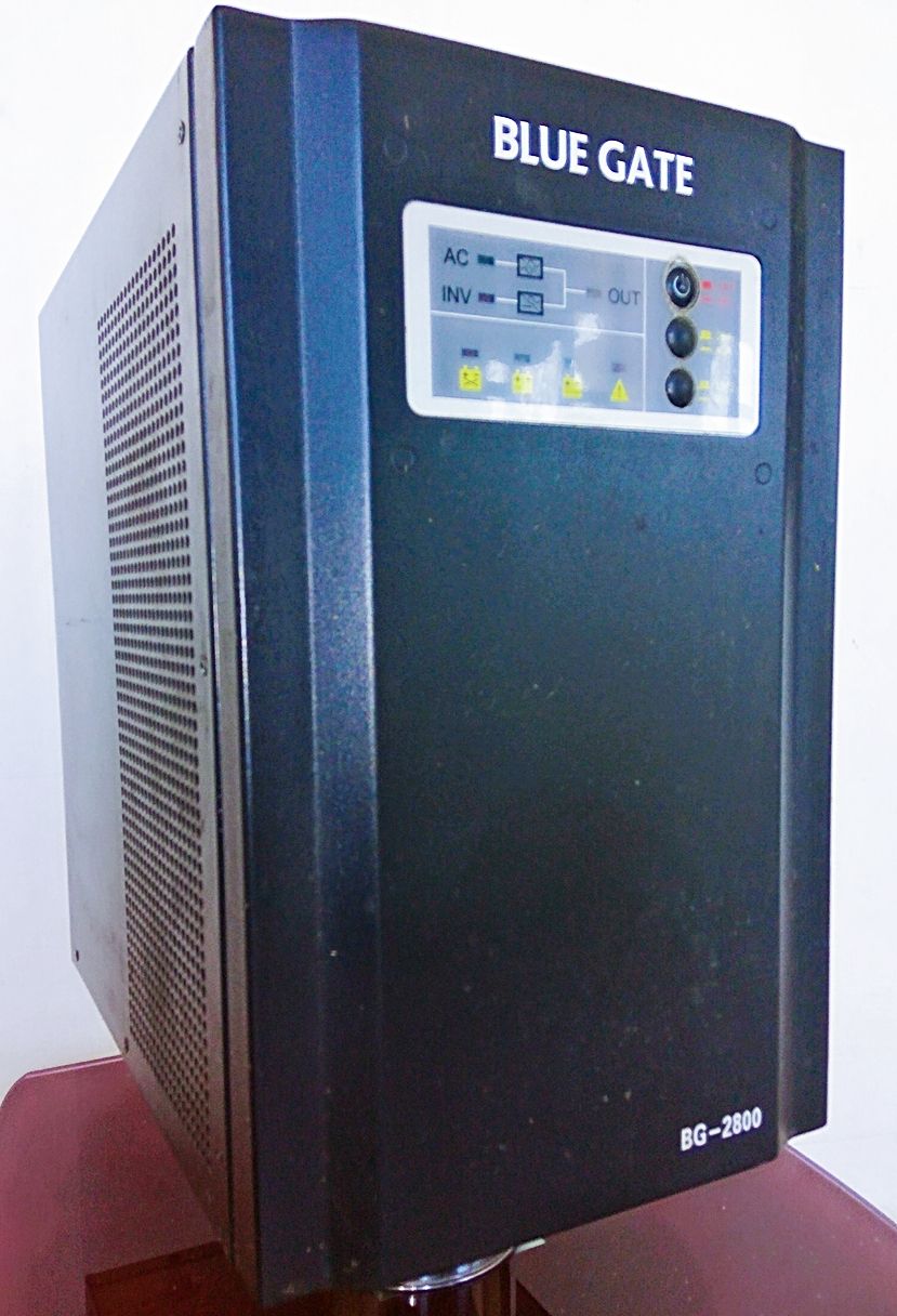
 [Original picture taken with my Redmi Note 3 Pro Prime: 2.8KVA Blue Gate Sine Wave Inverter]
It was this Rock 'n Roll band that popularised AC-DC because most people never heard of the War of Currents. War of Currents is the name given to the battle for supremacy between the American greatest inventor, Thomas Alva Edison (February 11, 1847 – October 18, 1931) and his Serbian-born arch-rival Nikola Tesla (1856 - 1943). The feud between the two had many facets which include the fact that Tesla once worked for Edison and was cheated by Edison, they had disagreement in scientific methods, lifestyle and so on. In the end, it was disagreements on how best to get electricity into homes that were the biggest disagreement.
Nikola Tesla believed that the best way to deliver electricity to homes was through the transmission of Alternating Current (AC) while Thomas Edison found Tesla's proposition "utterly impractical". Edison's proposal was the transmission of Direct Current (DC). While Edison tried different means, including some pretty devious ones such as electrocuting an elephant and supporting the use of AC for execution of the death penalty, Tesla ended up winning. He won because, in spite of the danger of electrocution, AC transmission offers various advantages in the transmission of electric power over DC transmission. A comparison between AC and DC transmission would reveal these advantages.
| S/No | Factors | AC | DC |
|---|---|---|---|
| 1. | Conductors Required | Requires three conductors | Requires two conductors |
| 2. | Inductance, capacitance etc. | Existence of inductance, capacitance, phase displacement and surge problem | No such problems |
| 3. | Skin effect | Skin effect exists | Absence of skin effect, so the whole cross-section of the conductor is utilised |
| 4. | Corona effect | More corona effect | Less corona effect and hence more efficiency |
| 5. | Potential stress on insulators | High | Low |
| 6. | Voltage regulation | Low | High due to absence of voltage drop |
| 7. | Transmission Distance | Maximum distance of transmission is high | Limited to a one-mile radius |
| 8. | Compatibility with Transformers | Compatible with transformers and therefore capable of being changed in power transmission | Not compatible with transformers |
| 9. | Switches and Circuit Breakers | Efficient switches and circuit breakers | Switches and circuit breakers with limited capabilities |
| 10. | Maximum Transmission | Can be generated at up to 11 kV and 21 kV in some countries | Can be generated at high voltage but cannot be stepped down |
Table 1.1: Comparison between AC and DC
A close look at Table 1.1 would have you wondering why people did not see it that AC transmission was "impracticable" as Edison put it since DC offers so many advantages and such few risks! Well, it turns out that AC has all the advantages that count when it comes to transmission of electricity over long distances, since we must generate electricity far from users we must transport it to our homes. However, we cannot just allow high voltage alternating currents to flow through our home appliances, frying our circuits. Therefore, we must find a convenient way to convert AC to DC in our appliances. This is the job of rectifiers which we discussed here.
Things, however, are never that simple. If we somehow manage to generate DC voltage in our home by using Solar panels, we may not be able to use the DC in our appliances because these appliances have been designed to take in AC and convert to DC for use. Therefore we cannot change the input anytime we want. This is why we use inverters - machines which take DC voltage and convert it to AC voltage so that our appliances can receive the type of voltage with which it was designed to function. Let us see what the inverter is all about.
Inverting with Magic Hands
We know that DC is current moving in one direction much like soldier ants on a mission. AC, on the other hand, is current that is flowing in cycles, which means that it flows in one direction then changes and flows in the opposite direction. In Nigeria and many other countries except the US, the AC changes direction 50 times per second.
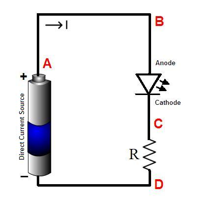
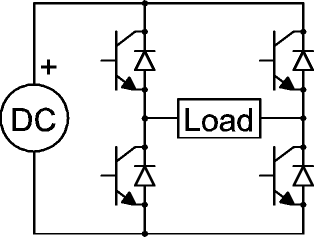
This alternation is the reason we say that the frequency of the alternating current is 50 Hertz (in Nigeria and neighbouring countries) and 60 Hertz (in the US). So, if you are a magician with swift fingers, all you have to do is stand at the output of the battery in the DC circuit of Fig 1.1 and switch the A terminal to the other terminal, fifty times per second and you would have succeeded in converting the DC circuit to an AC circuit. Excellent.
Even though you have invested your magic in converting the DC to AC, the AC you have obtained is not quite the way it is meant to be because the waveform of such an AC is not sinusoidal. In other words, the alternation of the current would be quite abrupt as the current switches direction suddenly, and this can be quite brutal to electronic equipment, often causing damage to home appliances. This is the kind of AC obtained by using a mechanical inverter built with an electric motor or a variety of automated switching device.
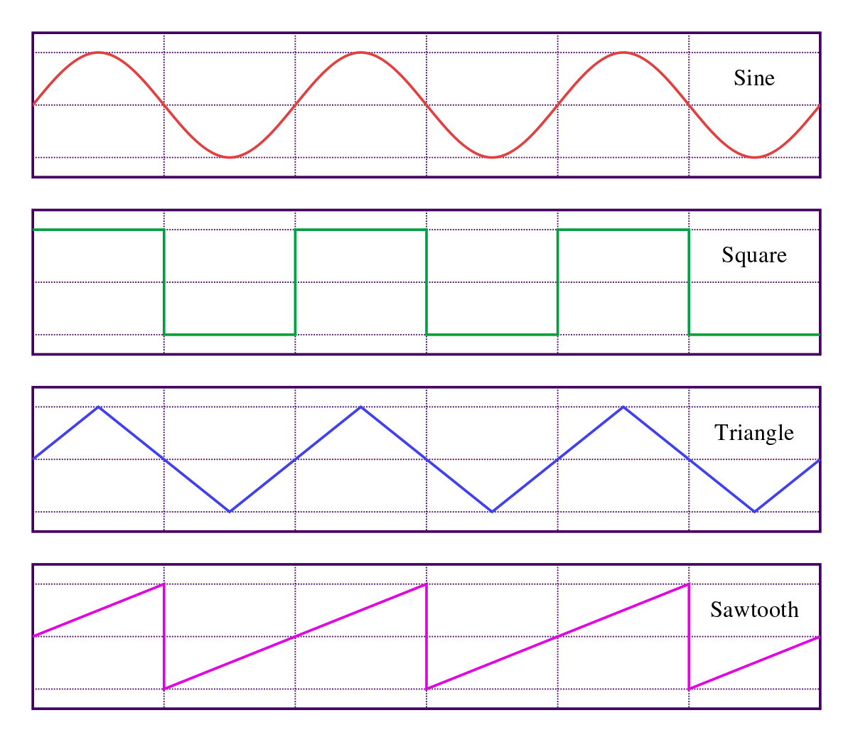
The waveform of such an inverter is either a saw-tooth shape or a square shape as shown in Fig. 1.2. Sometimes it is a triangular waveform. However, what is desired is a sine wave in which the current changes direction in a slow and smooth manner as shown in the sine wave. While an inverter that produces the square, triangular, and saw-tooth waveforms are still being manufactured and used today, our focus is on the type that produces a sinusoidal waveform.
Types of Inverters
Inverters can be classified based on the shape of the waveform that the output AC takes or based on how the inverter is connected to the home. Based on these two criteria, the following are some of the classifications of inverters:
- True/ pure sine wave inverters
- Quasi/ modified sine wave inverters
- Standalone inverters
- Grid-connected inverters
Grid-connected inverters are such excess power generated from say a solar panel installed in the home, is sold to the utility through the grid. However, this connection may cause problems because if there is a power outage from the network, then the home that uses a grid-connected inverter would be in a blackout, just as if there was no solar power generation system installed in the house. To solve this problem, there are bi-modal or bi-directional inverters which can work as either standalone or grid-tied but never as both.
Pure Sine Wave Inverters
We have talked about almost everything except how to arrive at an inverter that gives AC with a pure sine wave as an output. The process is slightly complicated but let us try a simple explanation. Pure sine wave inverters employ the concept of Pulse Width Modulation(PWM). Pulse width modulation is a technique employed in communication engineering to encode messages in a pulse signal. Even though this is the main application, it is also useful in pure sine wave inverters. The process used in the inverters to convert DC to AC using PWM is two folds:
- Generate the DC as pulses
- Averaging the pulses.
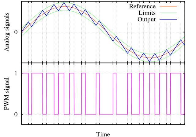
This is how PWM works. The DC voltage fed to the inverter input is produced as a series of DC pulses with varying widths. The width of-of the pulses is made wide for the areas where the sine wave should have a higher amplitude. The second step is to obtain the average of these pulses. The result is a sine wave such the one below:
In practical terms, the process described above is implemented with a Full Bridge Inverter Circuit The circuit is made up of four switches, a DC source and load connected as Fig 2.1 here.
From Fig 2.1 b, when the transistor switches D1 and D2 are closed, current flows through the load in one direction. When D1 and D2 and closed so that D3 and D4 are closed, the current would flow in the other direction, thereby producing a square wave the likes of which we discussed earlier. To convert this to a smooth sinusoidal waveform, we employ two additional devices called comparators. The output of one is connected across g1 and g4 with an additional NOT gate connected on one of the legs of the comparator output. The output of a second comparator is connected between g2 and g3 with an additional NOT gate on one of those comparator outputs. The function of the NOT gate is to ensure that when the comparator is turned on, only one of D1 and D4 is closed. The same thing applies to D2 and D3.
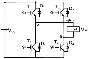
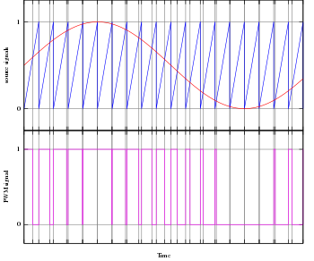
The first comparator takes a sine wave and a triangular wave as inputs and compares the signal whereas the second comparator takes an inverted sine wave and a triangular wave as inputs. The logic of the comparison is as follows:
- If the sine voltage amplitude is greater than the triangular voltage, output 1; otherwise, output zero. That is
- Vsine > Vtrian = 1
- Vsine < Vtrian = 0
When the output of the comparator is 1, D1 is turned ON while D4 is OFF. This logic produces a waveform such as the one below:
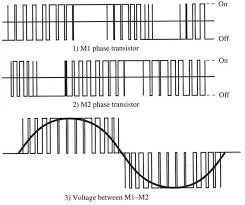
- The above comparison is performed by the second comparator using an inverted sine wave, generating its own set of square waves while turning D3 ON at the same time as when comparator 1 turned on D4 and turning D2 ON at the same time with D1.
Finally, since the output voltage, Vac, is the voltage between A and B, we find the net voltage by between point A and B using the waveform as follows:
As shown in the waveforms above, we have succeeded in generating a sine wave from the pulses. However, our work is not done. To smooth off the sine wave, inductors are connected to the output to smooth off the current and capacitors are also connected to smooth off the voltage. The finer the triangular wave, the more accurate the pulse train we be in producing the sine wave.
We must not forget to mention that a transformer is used in an inverter to step up or step down (usually step up) the input voltage to a higher voltage (up to 220 or 240 V) used by home appliances. We know from the law of conservation of energy that we cannot produce extra power apart from the one at the input. Therefore, even though the voltage of the output AC is increased significantly, the current must be reduced by corresponding amounts so that the output power remains the same or less than the input power due to inevitable losses.
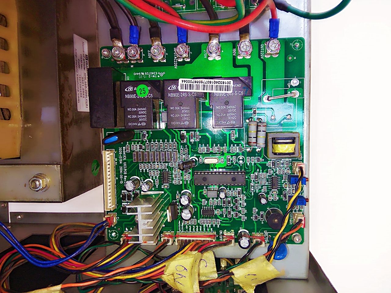
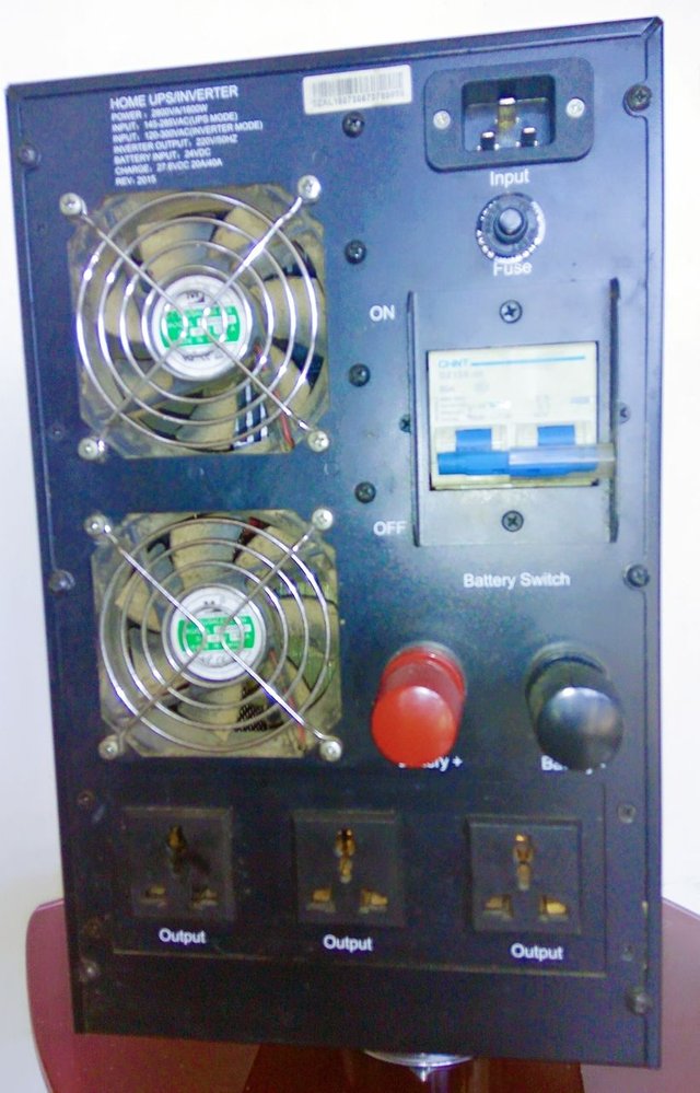
It is always lovely sharing these ideas with you. If you read until this point, congratulations: you are a geek! Thank you for your time. Below are pictures of a 2.8 kV Pure Sine Wave Blue Gate Inverter I used before replacing it.
[Original pictures taken with Xiaomi Redmi Note 3 Phone by @churchboy]
[Original pictures taken with Xiaomi Redmi Note 3 Phone by @churchboy]
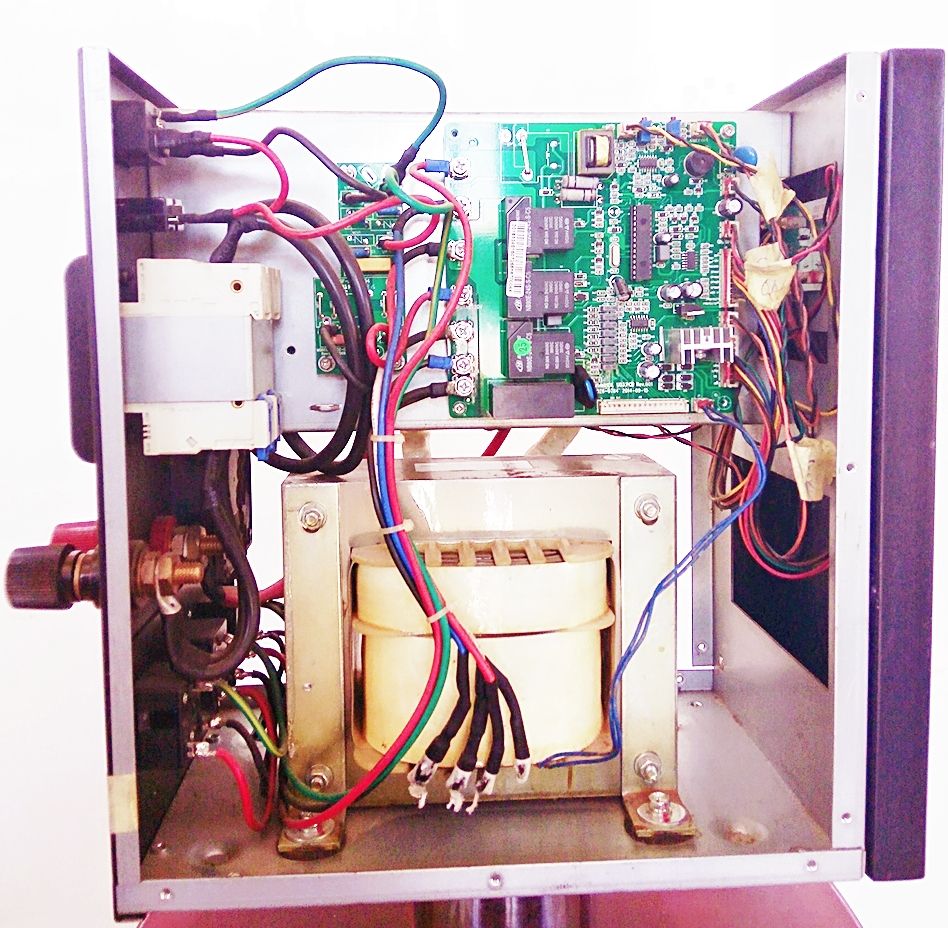
[Original pictures taken with Xiaomi Redmi Note 3 Phone by @churchboy]
References
- Wikipedia | Square Wave
- Spark Fun | Pulse Width Modulation
- Explain That Stuff | How Inverters Work
- Solar Facts | Inverters
- Electronics Tutorial | Single Phase Full Bridge Inverters
- Learn Engineering | How Inverters Work
If you write STEM (Science, Technology, Engineering, and Mathematics) related posts, consider joining #steemSTEM on steemit chat or discord here. If you are from Nigeria, you may want to include the #stemng tag in your post. You can visit this blog by @stemng for more details. You can also check this blog post by @steemstem here and this guidelines here for help on how to be a member of @steemstem.

Howdy churchboy, how goes it in Nigeria?
Good post once again, though......of course I have something to add.
I believe one of the biggest differences between Edison and Tesla was that Edison was a thief, he contracted with Tesla, Tesla fulfilled his part much to Edison's surprise and Edison refused to pay him. Conversely, Tesla upon hearing the contract he signed with Westinghouse would result in employees being fired, Tesla tore up the contract. Edison was very much about his own fame and wealth, Tesla was trying to serve humanity. In fact, the two could not be more opposite if one were white and the other black. Tesla is a hero while Edison to me is an arch-villain.
"It was this Rock 'n Roll band that popularised what is known as the War of Currents" ~ I think you may have meant to say something else. The RnR band ACDC did not, as far as I know, and I could be wrong, take their name from the War of Currents of seven decades prior. In the 1970s England, someone who was ACDC was bisexual and it was that slang usage that the inspired the band to take the name ACDC.
I also question your switch light analogy. Switching an AC power source off and on at 50 times per second I doubt would produce direct current, perhaps if you were able to cut the wavelength in half and disallowing the negatively charged pulse, but that would require some serious timing with that magic.
And the frequency that you speak of 50Hz and 60Hz is actually speaking of the properties of the magnetic wave. All energy on the electromagnetic spectrum has a frequency(Hz) and a wavelength(meters)
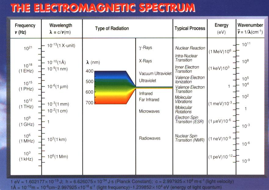
In this chart, you can see that radio waves are in the millions of Hz, much much higher than electricity at 50-60Hz which is down in what is called the "super low frequency" and has a wavelength around 10,000,000 meters in size. The larger the wavelength the lower the frequency, the smaller the wavelength the higher the frequency. For example, Gamma rays at the opposite end of the spectrum have a wavelength of 1 pm (picometer= 0.0000000000001 meter) and a frequency of 300Exahertz. 1 Exahertz is exactly one quintillion Hertz. 1 EHz = 1 x 10^18 Hz.
So electricity at 50hz means that wavelength of 10,000,000 meters passes (peak to peak) a single spot 50 times per second.
Alternating current means the current alternates direction, while Direct Current can only flow in one direction. In other words, AC switches from V- to V+ to V- to V+, while DC is V+. One revolution you see in an oscilloscope such as the image down below equals 10,000,000 meters in length.
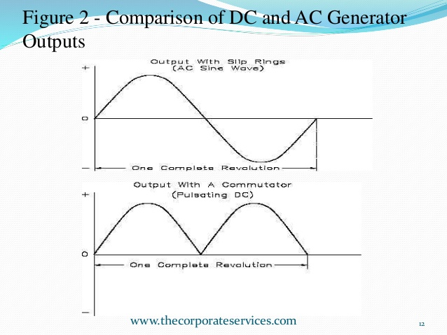
As you can see by the above image, DC has a wavelength too.
Peace brother
#daemon-nice
I should have known I was in for a surprise tutorial when you suggested last time that I should talk about the history of those two inventors. I was not there at the time but everything you wrote about the feud between Tesla and Edison seems to be spot on. Yes the story has it that Edison tried various dubious means to win the war. And yes, the two inventors couldn't have been any different, even their pictures say so.
When I say that ACDC popularised the war of current, I meant that the rock band is the only ACDC that most ordinary people know. The war of current is not a general knowledge. However, I am glad that this has made you talk about the bisexual connection. I did not know this prior to reading your comment.
Concerning the 50 Hertz, I thank you for the electromagnetic analogy. I'm sure you meant to point out that magic hands are not enough to convert DC to AC and I agree. That's why we use pure sine wave inverters :)
Now, let me go and look for steem power to upvote your beautiful comment because my steem power is hardly enough :). Thank you for the time you spent explaining these things. You may have just inspired another post.
Oh, we are doing very well here in Naija :). How are people of the earth? :)
Well, I am happy that you received my "surprise lecture" with the goodwill I intended when I wrote it.
Concerning the 50Hz, that isn't an analogy as much as it is accepted science. I know there are differences regarding electrical theory between electricians and physicists. I assume you are coming at it from an electricians perspective. I myself only started studying electricity a couple of years ago as I became fascinated by the electric universe paradigm and wanted a deeper understanding. Since then I have read a great deal on Maxwell and Faraday, Hertz, Steinmetz, Tesla. Have studied it from the Physics perspective and the electricians perspective(IEEE). The problem with the physics is they rely too much on maths and not enough on real-world observation.
It pleases me greatly to have inspired you, that is truly a special gift; inspiration that is. I enjoy reading your posts and in particular, this line of communication opening up between us.
In my part of the Earth, it is cold and snowy. Would you say your weather is cooler than normal, about normal or warmer than normal?
Peace
#daemon-nice
You should publish this article in IEEE :) thanks for this valuable information, good work!
Thank you, @cemke. I'm afraid that the post isn't up to IEEE standard. Thanks for the compliment and for visiting my blog :)
You are wellcome my friend! You can modify it according to IEEE Format :)
Thank you for replying. Well, I hope more people like it here first :)
Churchboy! Though I'm completely lost, I seen you and said oh my I have to look 😁 I've missed you and your posts, but so happy to see you. Great post my dude! 💞
Hey Kristan! It has been ages. Whatever happened. I have missed you! Thank you so much for coming around. These science posts are taking too much time. Maybe I should go back to stories and come back to my friends. It is so nice to see you. I hope you're doing great.
I am sir anddd Id love to see some of your stories again 😘😁
Surely, you shall see one soon. Thank you.
Damn I was so bad in science :p Didn't understood much but still upvoted due to the efforts u put in there :) Keep it up
Hahahaha. I don't think I was good at it either so I usually make efforts to write it the way most people like me would understand. Thank you so much for your support. You're appreciated.
Wow! Very educative post. I have learnt something very important. knowledge they say is power and you've just given me "power" via this interesting post.
Good job!
Thanks bros. You're appreciated.
Nice article there, explaining the conversion from DC to AC using inverters. I like the song by AC/DC. Haha! Upvoted!
Thanks, my brother. I just found out a out the rock band. Thank you for your comment and support. I hope things are looking up in Singapore. All the best.
I am interested in your writing which says Thomas Alva Edison (February 11, 1847 - October 18, 1931) and Serbian rival Nikola Tesla (1856 - 1943). The dispute between the two has many aspects including the fact that Tesla once worked for Edison, lifestyle and so on. In the end, it is disagreement about the best way to house to the houses which is the biggest disagreement. I think they are at odds for a great life that can change the world. Now return to us how we use well the findings of these two people.
Thanks a lot for your comment. Much appreciated
A good piece of writing even though with some gray areas. Nevertheless, please keep up the good work :)
Hey, thanks a lot for visiting my blog. I appreciate it. If you could point out the gray areas, perhaps I can change them to either black or white :)
But seriously, I would appreciate it if you could point them out. Thanks a lot.
Great Post. Reminds us of the dirty games that were played.
Inverters have evolved like any other technology. I like what grid-connected inverters offers especially for countries with low generation capacity.
Yes. Thanks a lot.