SteemTrain Article 3 Timers [TON] / [TOF] / [RTO]
RSLogix 500 / Micrologix / Rockwell

ARTICLE 3
Timer On [TON] / Timer Off [TOF] / Retentive Timer On [RTO]
Ok fellow Steemian techies, it has been some time since I have made a SteemTrain post. My main goal coming onto the Steemit platform was to share the coding knowledge I have ascertained over the years. Shortly after beginning to post I got swept up in the cryptocurrency controversy and strayed away from my roots. I apologize to those of you who have patiently been waiting for the timers and counters article. Also as I began to lay this article out I realized it would better suit the reader if I were to break apart the counter and timer instructions into their own respective articles.
This article was written with the use of Rockwell's RSLogix500. Although the concepts will ring true throughout the industry. They will be geared towards using the Rockwell Platform.
Let's begin with the Timer On [TON]. First of all timers are a bit different in respect to the fact, each timer utilizes 3 words of data as soon as it is dimensioned. Unlike the [XIC] / [XIO] instructions which are 1/16 of a word each. So we want to be sure that we only dimension the timer data file for exactly the number of timers you will be using in a said project.
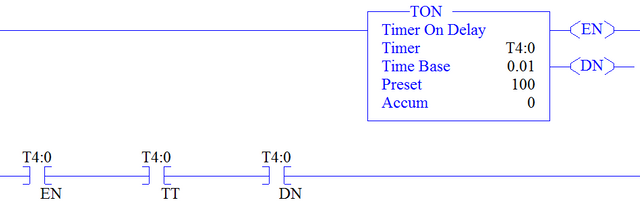
In the image you can see what the [TON] instruction looks like on RSLogix500. The instruction requires 3 parameters be set. The first parameter is the location of the timer. In my case, I only set the T4 data file to 1 element. My only timer is T4:0, so this is what I will use for the Timer parameter. The next parameter is the Time Base parameter. This parameter is in seconds. On a MicroLogix1400 you can choose from 1.0 / 0.01 / 0.001. The final parameter is the Preset parameter. The preset parameter is expressed as a static or variable value. This parameter is what determines the length of delay the timer will have.
In the image above, of the [TON] instruction, I have also included the bits that can be used within your code. These include the [T4:0.EN] / [T4:0.TT] / [T4:0.DN]
The .EN bit is TRUE if the timer is currently enabled. Meaning the rung the timer resides on within the code is currently true.
The .TT bit is TRUE if the timer is currently actively timing. Meaning the rung the timer resides on within the code is currently true, and the timer Accum parameter has not yet reached the timer Preset value.
The .DN bit is TRUE if the timer Accum parameter has reached the Preset parameter value. Meaning the rung the timer resides on is TRUE and remains TRUE for at least the Preset amount of time.
If at anytime, the rung on which the timer resides goes FALSE, The .DN, .ENand .TT control bits all reset to FALSE regardless if the Accum parameter has reached the Preset parameter value or not. Also the .ACC(Accum) value is reset to 0.
Let's move to the Timer Off [TOF].
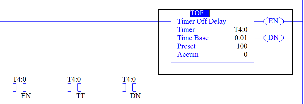
In the image you can see what the [TOF] instruction looks like on RSLogix500. The instruction requires 3 parameters be set just the same as the [TON]. The first parameter is the location of the timer. In my case, I only set the T4 data file to 1 element. My only timer is T4:0, so this is what I will use for the Timer parameter. The next parameter is the Time Base parameter. This parameter is in seconds. On a MicroLogix1400 you can choose from 1.0 / 0.01 / 0.001. The final parameter is the Preset parameter. The preset parameter is expressed as a static or variable value. This parameter is what determines the length of delay the timer will have. This looks almost identical to the [TON] instruction except for where it says TOF and Timer Off Delay. Actually the timer does function identically with exception to the .DN bit. The .DN bit is TRUE immediately when the rung the timer resides on goes TRUE.
In the image above, of the [TOF] instruction, I have also included the bits that can be used within your code. These include the [T4:0.EN] / [T4:0.TT] / [T4:0.DN]
The .EN bit is TRUE if the timer is currently enabled. Meaning the rung the timer resides on within the code is currently true.
The .TT bit is TRUE if the timer is currently actively timing. Meaning the rung the timer resides on within the code is currently true, and the timer Accum parameter has not yet reached the timer Preset value.
The .DN bit is TRUE immediately upon the rung the timer resides on going TRUE. The .DN bit remains TRUE while the timer Accum parameter has not reached the Preset parameter value. Meaning the rung the timer resides on is TRUE and remains TRUE for at least the Preset amount of time.
If at anytime, the rung on which the timer resides goes FALSE, The .DN, .EN and .TT control bits all reset to FALSE regardless if the Accum parameter has reached the Preset parameter value or not. Also the .ACC(Accum) value is reset to 0.
Let's move to the Retentive Timer On[RTO].
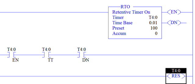
In the image you can see what the [RTO] instruction looks like on RSLogix500. The instruction requires 3 parameters be set just the same as the [TON] / [TOF]. The first parameter is the location of the timer. In my case, I only set the T4 data file to 1 element. My only timer is T4:0, so this is what I will use for the Timer parameter. The next parameter is the Time Base parameter. This parameter is in seconds. On a MicroLogix1400 you can choose from 1.0 / 0.01 / 0.001. The final parameter is the Preset parameter. The preset parameter is expressed as a static or variable value. This parameter is what determines the length of delay the timer will have.
In the image above, of the [RTO] instruction, I have also included the bits that can be used within your code. These include the [T4:0.EN] / [T4:0.TT] / [T4:0.DN]
The .EN bit is TRUE if the timer is currently enabled. Meaning the rung the timer resides on within the code is currently true.
The .TT bit is TRUE if the timer is currently actively timing. Meaning the rung the timer resides on within the code is currently true, and the timer Accum parameter has not yet reached the timer Preset value.
The .DN bit is TRUE if the timer Accum parameter has reached the Preset parameter value. Meaning the rung the timer resides on is TRUE and remains TRUE for at least the Preset amount of time just like the [TON] instruction.
The difference between the [TON] instruction and the [RTO] instruction is the fact that even when the rung the [RTO] instruction resides on goes FALSE, the Accum parameter retains it's value. The only way to get the Accum parameter to reset to 0 is to issue a [RES] (Reset) instruction on the timer. I have demonstrated this on the last rung in the RTO instruction image.
That wraps up this article. Look for the Counter article next time.
Until then Keep it on the rails...
Relay
LTC LdUmxBAL3txed6Qc4FRPteZ9NH3Fginvz3
BTC 1HgH6FEiCFwBWM5kk93xFeENwFNhcMS1wW
Doge DFNS5diVXAHhtLbhZyqsuPeVofHnPKMWMy
Cool!
Resteemed, upvoted & followed you @jamescash!
Thanks for availing the 3 in 1 FREE Giveaway Package!