Switch Mode Power Supply - That Supply unit that served you alot without you knowing
Do you know that the essential part of a computer system is the mother board. It holds many of the important components (such as the CPU, memory and connectors for the I/O devices) of the computer together. But as important as it is, if power is not supplied to it, the entire components within its circuits stay inactive and in short the system does not perform its functions. I am sure you all know what device is responsible for such task. Yea, it is the Power Supply Unit (PSU). Most of the internal components of the computer system can only be powered by DC voltage and the power available at our socket outlet is AC voltage, so the conversion process is carried out by the PSU. The unit converts the AC mains (230V) to lower regulated DC voltage to power up the internal components of the system. Many of PSUs used in modern personal computer complies with the ATX specification Now to real question for the day, do you know what type of PSU is used in the computer system? Yea, it is the Switch Mode Power Supply (SMPS). This type of PSU has not only found its usefulness in computer system, also in some of the devices we are familiar with, like our mobile phone chargers, laptop charger, solar lamps, security systems (closed circuit cameras) and so on. Before going into detailed explanation of what SMPS is, its types, its principle of operation, advantages and disadvantages, I will take you on a power conversion trip. Power conversion in electrical engineering is the transformation of electrical energy from one form to another usually between AC and DC power. The conversion is necessary because of each power advantages over the other. The conversion process is made possible by a converter circuit known as the voltage converters and these converter circuits can be categorized into four forms based on the power input and output. The SMPS actually belongs to the DC - DC converters but since the power available at our socket outlet is usually AC power, so it will be required to convert it to DC first using AC - DC converters. For now, I will talk on the two converters stated above and maybe in another post, I will discuss in details the remaining converters because of their complexity. AC - DC Converter The most common type of AC - DC converter is the full-wave bridge rectifier. This converter circuit unlike the half-wave rectifier utilizes four diodes which uses the positive half as well as the negative half to permit constant flow of energy from the input to the output and a capacitor to filter the ripple voltage. It is capable of directly rectifying high AC voltage and then charges the capacitor to produce a voltage source DC - DC converters. Most SMPS make use of DC power from a full wave bridge rectifier as voltage source. DC - DC converters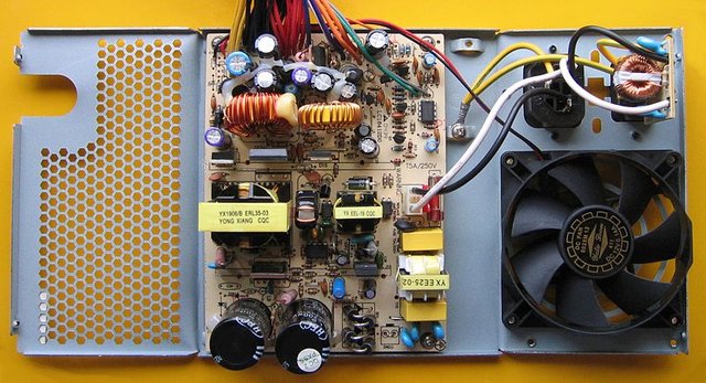
ATX PC Power supply unit Image source: Wikimedia under Creative Commons Attribution-Share Alike 3.0 Unported
This converter can be grouped into two sections; the one that offers electric isolation and the ones that don't. Isolation comes in place when a transformer is used before the converter. The simplest type is the half-wave rectifier which makes use of single diode (this allows only the positive half of AC current through) and a capacitor (takes charges to produce a constant DC voltage).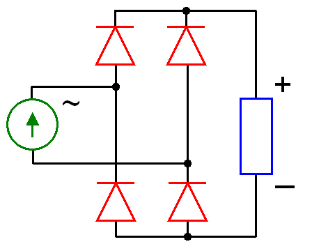
Full wave rectifier Image source: Wikimedia under Creative Commons Attribution-Share Alike 3.0 Unported
Other DC converter includes the following:
Unlike AC - DC converters, this converters are solely used to supply a continuous fixed voltage output from an unregulated voltage input. They can be grouped into two sections namely; linear voltage regulator and SMPS.

Linear voltage regulator
From its name, you can already guess what this converter function is, some of ours might have even worked with this component in the design of a regulated DC power supply before.

I will quickly use a simple discrete linear voltage regulator circuit to explain the concept.
Comparing this circuit with a voltage divider that makes use of two resistors (R1 & R2), R2 is replaced with a zener diode D1 because in real life cases, the supplied voltage Vin is not

always constant. And also the power transistors added, acts as emitter follower to reduce the internal resistance of the zener diode which cause the diode to operate at minimum current level ( mA). The output voltage of this regulator is the addition of the zener voltage Uz and the voltage drop Ube at the base-emitter junction of the transistor which is usually about 0.6. Let say for instance one is to design a 5V regulator, one can use a zener diode with 5.7V as its reverse voltage. When summed up with the voltage drop across the base-emitter junction of the transistor, this gives out 5.1V as its output.
The arrival of Integrated Circuit as explained here by @doctorchungs has made linear regulator more efficient and easier to use compare to equivalent voltage regulator circuit made from discrete components like transistor, resistor, capacitor, zener diode and so on. The common linear voltage regulator found in the market today is the 78 series (positive output) and the 79 series ( negative output) with voltage level ranging from 5V to 24V. They only offer step down voltage regulation.

Switch Mode Power Supply
Why then do we need a SMPS if we already have a linear voltage regulator? Linear regulator are only capable operating in application wheere low power output are required and also the transistor within it design, generates alot of heat when continually biased in its linear region resulting in ppwer wastage and poor efficiency. How then do SMPS overcome this limitation? The transistor used in SMPS for switching, operates in the On and Off states which produces lower power dissipation and of course a higher efficiency compared to the linear regulator. The operation of the transistor is similar to that of a switch. When closed, it conduct current and the voltage drop across it is minimal and when opened, no flow of current..jpg)
A switched-mode power supply (SMPS) is an electronic circuit that converts power using switching devices that are turned on and off at high frequencies, and storage components such as inductors or capacitors to supply power when the switching device is in its non-conduction state.
Techpedia
A basic switching converter consists of power switching stage and the control circuit. Power conversion from the input voltage to the output voltage is made possible by the power switching stage while the control circuit controls the turning Off and On (duty cycle) of the switching device. Some of the major components used in designing are inductor, capacitor, diode and transistors.
When comparing SMPS with linear regulator in term of its output voltage, they are capable of offering more than step down voltage regulation, they offer also step up regulation and the combination of both. These regulation can be achieved using the three basic topologies namely; buck, boost and buck-boost converter.
| Topology | Output voltage level | polarity |
|---|---|---|
| Buck | Lower than input | positive |
| Boost | Higher than input | positive |
| Buck-boost | Higher or Lower than input | negative |
Visit here to learn more about the operation of the three basic topologies.
With the understanding of the operation of three topologies, other topologies like the flyback converter, forward converter or push-pull converter can be easily. What makes these topologies different is the inclusion of transformer for energy storage and electric isolation (this separates the input supply from the output).

How SMPS performs their wonders
Well, to have a vivid understand about this PSU, one must know how energy are stored and used, and how these components interact with one another. All modern PSU that utilizes SMPS have the same mode of operation, be it forward, flyback , push-pull configuration.
In theory, their operation can be grouped into four stages. This stages includes the rectification stage, inverting stage, voltage converter/rectification stage and regulation. Remember that the supplied voltage can either be a DC source or rectified DC from the mains.
 Basic block diagram of SMPS Image source: Wikimedia under CC BY-SA 3.0
At the rectification stage, the 230VAC supplied by the mains is rectified by the retifier circuit that produces an unregulated 325VDC (230 × √2) that is sent to a filtering capacitor commonly known the buck capacitor. A DC source can also be used to power this same PSU, it will remain unchanged after passing through the rectifier circuit.
The inverter stage converts the unregulated DC voltage to AC by running it through an oscillator which makes use a ferrite transformer. Why then was the power rectified in the first place if it will still be inverted again? As you all that the frequeny of the power available at the main is 50/60Hz, this frequency must be step up by the oscillator to a frequency of about 20kHz which is inaudible to humans.
Also within the oscillator is the switching device (transistor) implemented.
Regulated high AC voltage at high frequency produced by the the oscillator is step down to a lower level by a high frequency transformer and then rectified. The voltage conversion and rectified occurs in the voltage converter/rectification stage. The essence of the voltage step down is for the isolation of the output voltage from the high voltage. With the aid of a filter, the rectified output is smoothed out.
The final stage which is the regulation stage is responsible for keeping the regulated voltage constant at all time irrespective of any fluctuation that occurs at the input. This is done by comparing the output voltage with the reference voltage with the aid of the feedback circuit within it.
Drawback
As effective as SMPS are, they are very expensive compared to other forms of regulated power supply such linear supply. If you check out some of the images of SMPS i used above, you will see how bucky the components are packed together. This indicates how complex the circuit design will be and i can tell you as an average electronic hobbyist, it can one up to a month to fully interpret and understand the circuit diagram. They also generate electromagnetic interference and causes harmonic distortion in the process.
In conclusion, SMPS makes use of transistor switching to provide the regulated DC output voltage from an unregulated DC input voltage. This transistor operates in its switching mode by simultaneously turning On and Off at a high speed which produces low power dissipation.
These PSU can be found all around us as they have replaced all kinds of linear AC-DC power supply. They can be seen in our television set, laptop charger, mobile phone charger, amplifier and so on. Advantages why SMPS usefulness supersede other forms of PSU is its higher efficiency, low power loss and and its small size.
References
Wiki Switch Mode Power Supply
If you write STEM (Science, Technology, Engineering, and Mathematics) related posts, consider joining #steemSTEM on steemit chat or discord here. If you are from Nigeria, you may want to include the #stemng tag in your post. You can visit this blog by @stemng for more details. 
I'm a proud member of @promo-mentors where you get mentored and guided on how to make quality posts on steemit amongst other benefits. Do join us on discord. We anticipate your arrival.

Wow that's my final year project more than 20 years ago!
Had to build a high efficient SMP supply!
Brings back memories... 😀
20 years is a long time. But we can always recall that things that made an impact on us.
Hi @sunkanmi02!
Your post was upvoted by utopian.io in cooperation with steemstem - supporting knowledge, innovation and technological advancement on the Steem Blockchain.
Contribute to Open Source with utopian.io
Learn how to contribute on our website and join the new open source economy.
Want to chat? Join the Utopian Community on Discord https://discord.gg/h52nFrV
Hey, though I appreciate this post and have given it a steemstem upvote, it comes very close to plagiarism at points. For example:
Original
My advice to avoid being blacklisted is to try and be a bit more creative and original with your content rather than just re-writing information from some websites, which is the feeling I get from this post.
The more original a post is the better rewarded it gets and the more interesting it is to the readers.
Good luck
Thanks, i will try to avoid that next time