CHAPTER 3::STABILITY WITH VSC-HVDC TRANSMISSION
Voltage source converter:
HVDC systems based on voltage sourced converters normally use the six-pulse connection because the converter produces much less harmonic distortion than a comparable LCC and the twelve-pulse connection is unnecessary. Most of the VSC HVDC systems built until 2012 were based on the two-level converter, which can be thought of as a six-pulse bridge in which the thyristors have been replaced by IGBTswith inverse-parallel diodes, and the DC smoothing reactors have been replaced by DC smoothing capacitors. Such converters derive their name from the discrete, two voltage levels at the AC output of each phase that correspond to the electrical potentials of the positive and negative DC terminals. Pulse-width modulation (PWM) is usually used to improve the harmonic distortion of the converter. The detailed description of VSC-HVDC technology was reported in [2], including its basic theory, characteristics and performance. But it aims to general readers, like grid operators, investors, and anyone wanting to know VSC-HVDC.
Stability with VSC-HVDC transmission:
It is needed to have a stable and reliable control of real and reactive power as power system is highly dependent on it. Losing its control leads to collapse of the system. Voltage source converter transmission system has the capability to change its working point almost within its capability curve. VSC provide s best support to the grid with active and reactive power, during stressed condition. In comparison with the other cases, mix active and reactive power in the best solution then to active or reactive power only. VSC-HVDC plays a key role at the time of grid restoration consideration as it can control voltage and stabilize frequency when active power is available at remote end. VSC transmission can also capable of influencing the asynchronous grid conditions, power quality and harmonic problems. N-1 criterions or similar can be used to establish the maximum load that can be critical grid can transfer. VSC transmission can change its operating mode and strengthen the grid until other action restore the grid.
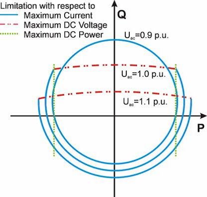
Capability chart of VSC transmission:
As the real and reactive power are independent of each other, VSC can theoretically operate at any point on P, Q plane. This P, Q characteristic is represented by a circle due to the operating possibility in any of the four quadrants. Factors affecting the affecting the operating range of converters are the maximum current through the converter switches and maximum DC voltage value. Maximum current limitation is needed to protect converter switches. Hence the VSC will operate within rated current corresponds to a circle of radius 1 pu (27).
Different grid configurations and stability issues:
There are two different aspect to consider. Firstly, the type of the system issues the VSC transmission system exposed to. There are three basic types:- 1.series connection of VSC converter and AC system
2.Parallel connection of VSC converter and AC system
3.Asynchronous infeed from the VSC converter into the AC system.
Series connection of VSC converter and AC system:
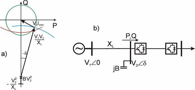
A situation revels that the power flow equation for receiving end power circle diagram combined with capability curve of VSC transmission show in figure will immediately curve of VSC transmission.
Parallel connection of VSC converter and AC system
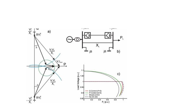
Connecting a VSC transmission in Parallel with the AC transmission and controlling the VSC transmission will have impact on the AC power flow to have a better utilization of AC system it is needed to vary the power factor of DC transmission system.
Asynchronous infeed from the VSC converter into the AC-system:
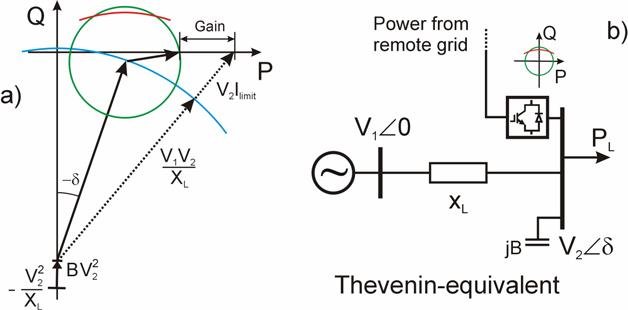
Many HVDC links are connected between asynchronous grids operating with different frequency. In the connection point where, active power is fed into the AC grid VSC transmission can add improved performance. If we study a Thevenin equivalent of an infeed shown in Figure the qualitative behavior of changing power factor in the VSC transmission can be studied. Compare the solid and dotted vectors in the diagram. By aligning the vectors by changing power factor we achieve maximum load ability.
Harmonics and filtering:
All power electronic converters generate some degree of harmonic distortion on the AC and DC systems to which they are connected, and HVDC converters are no exception. With the recently developed Modular Multilevel Converter (MMC), levels of harmonic distortion may be practically negligible, but with line-commutated converters and simpler types of voltage-source converters, considerable harmonic distortion may be produced on both the AC and DC sides of the converter. As a result, harmonic filters are nearly always required at the AC terminals of such converters, and in HVDC transmission schemes using overhead lines, may also be required on the DC side.
Summary:
In this chapter VSC ac side model is described and capability chart of VSC transmission is discussed. Different grid configuration of VSC along with the capability chart and stability issues are discussed.
References
- 1.“Improvement of Voltage Stability by Using VSC-HVDC” , H.F. Latorre,student member IEEE and M. Gandhari. Member, IEEE,IEEE xplore IEEE T&D ASIA-S1EF 2009, SEOUL, KOREA, October 26-30,2009.
2.Jiuping Pan, Reynaldo Naquin, Kailash Srivastava, Tomas Jonsson, Per Holmberg, Ying-Jiang Hafner “AC Grid with Embedded VSC-HVDC for Secure and Efficient Power Delivery” IEEE Energy 2030 Atlanta,IEEE xplore GA USA 17-18 November, 2008.
3.Text book “Voltage- Sourced Converters in Power Systems, Modeling, Control, and application” by Aminase Yazdani and Reza Iravani.
4.“Application Research on VSC-HVDC in Urban Power Network” by jian Luo, jianguo Yao, Di Wu, Chuanxin Wen, Shenchun Yang, ji Liu
WebSite Research Centre of State Grid Electronic Power Research Institute, Nanjing, China.
Image source
⬜️ Text book
⬜️ Microsoft power point