Understanding The Multimeter And Its Operation_A Beginner's Guide To The Multimeter
Once upon a time, many years ago, Engineers have to work with many meters to troubleshoot and test the conditions of electrical components in case of fault. But today, having just a handy meter(the multi-meter) can serve the same purpose all those different meters do; thanks to advancement in technology for such a relief
Introduction
Electrically, meter is an any instrument for measuring the magnitude or quantity of anything. Usually what a any meter measures is attached as a prefix to the word "meter". Example **volt**meter, the prefix is **volt** which is an S.I unit of voltage. Hence the voltmeter measures voltage. Another example is the **ohm**meter; ohm is the prefix and the S.I unit for resistance; hence, the **ohm**meter is an instrument(meter) for measuring resistance. Similar thing applies to ammeter. Amps is the S.I unit for current; hence the ammeter measures current. This meters are usually different and an engineer has to work with the three meters (ohmmeter, ammeter and voltmeter) almost simultaneously. This did not only create the burden of walking about with three meters to the site of the slightest electrical work you can imagine but also the inconvenience of interchanging between this three meters. The engineer might even need to bend down and pick the required meter depending on the site of work. with advancement in technology, came the evolution of a handy instrument which integrated the functions of the three afore-mentioned meters in just one meter. This meter is the multi-meter, it can measure both the current flowing through any component, the resistance of a resistor or material; and even the voltage supplied by a source or voltage across a circuit. All these can be done with just rotating the knob Incorporated in the multi-meter to the right position with reference to the quantity being measured_ voltage, current resistance. This means that the multi-meter serves as an ohmmeter, ammeter and voltmeter; the value of multi-meter to practically inclined engineers cannot be overemphasized, an engineer that does not know how to operate a multi-meter can be likened to a nurse that does not know how to administer injection. Multi-meter comes in two different types: the digital and the analogue multi-meterThe Operational Principle of A Multi-meter
To understand how multi-meters work, we have to use a reference which is the galvanometer. Because, the multimeter is basically an enhanced galvanometer, a galvanometer with improve features. A galvanometer consists of a needle pivoted on a coil which is attached to another coil that acts like a spring, the spring limits the movement f the needle o a predetermined scale. All these coils and needle are fixed between two permanent bar magnets The operation of galvanometer depends on three distinct principles which are the force in a current carrying conductor, the magnetic field created on a current carrying conductor and Hooke's law of elasticity. For easy understanding of this working principles, I will use a image to explain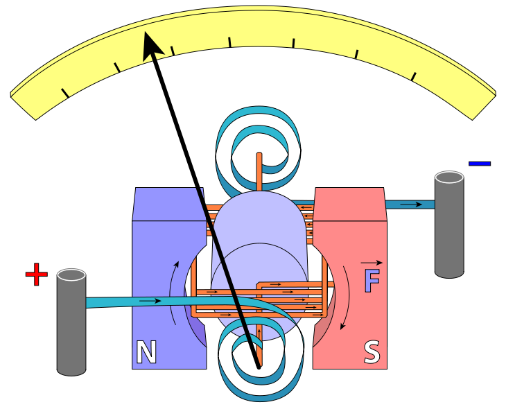
Source:[Wikimedia](
 )||License:[CC by SA 3.0](creativecommons.org)
The above is the internal structure of a galvanometer. Current flows from a source to the positive blue terminal, then from this blue coiled conductor in a spiral from to the orange coiled conductor, from the orange conductor to the other blue coiled conductor that leads to the negative terminal; the coiled blue conductors and the orange rectangular coiled conductor are electrically connected. The flow of current in a conductor generates a magnetic field which direction is giving by Fleming's rule. Hence a magnetic field is created due to the flow of current from the positive terminal through the negative terminal. The direction of this magnetic field is opposed by that of the magnetic field due to the bar magnets. This opposition causes the rectangular coiled conductor to twist, hence making the needle mounted on it to deflect along the scale. However, this deflection is opposed by the blue coiled conductor. The blue coiled conductor is patterned in such a way that gives it elastic feature and therefore behaves like a spring.
from Hooke's law which states that *the force needed to cause a compression or extension in a spring is directly proportional to the distance of compression or extension with respect to a reference point*.
Mathematically **F = Ke**
x = F/k
where
F= force
x = displacement or distance moved by the spring
K = elasticity of the spring
From this law, we observe that the distance moved by the blue spring depends on the total force on the needle pivoted on the orange conductor. So to increase the deflection of the needle on the scale, the force has to increased. To increase this force, is imperative to understand the force on a current carrying conductor.
This force is expressed mathematically as in below:
**F = BIL**
where
B = Magnetic field flux density
I = Magnitude of current flowing through the conductor
L = length of conductor
from this equations, it is visible that the internal force on the galvanometer depends on the current flowing through the blue conductors and the orange conductor, the total length of the blue conductors and the orange conductor, and the [magnetic field density](https://www.quora.com/What-is-the-physical-difference-between-magnetic-flux-density-B-and-magnetic-field-strength-H).
We can superimpose the equation from Hooke's law and the equation of the force on a current carrying conductor as below
**F= Kx**
**F= BIL**
**BIL=Kx**
making x the subject formula gives
**x=BIL/K**
So the last equation implies that the distance on which the blue spring conductor can move is directly proportional to the magnetic flux density(B), the magnitude of current(I) and the total length on the blue and orange conductors(L). And inversely proportional to the elastic constant of the blue spring(K)
However,the length of the blue and orange conductors are already constant for any galvanometer; so also is the constant of elasticity(K). So the variable quantities are the current(I) and the magnetic field flux density(B). So this whole equation is reduced as below for a given meter
**x= BI**
This implies the higher the current(I) the more distance(x) the blue spring conductor can extend. The limit of extension of this spring determines the deflection of the needle on the scale; the orange conductor to which the needle is pivoted on, is firmly fixed on the blue spring and is in a constant position with relation to the blue conductor. The only way the orange conductor can move is that the spring stretches due to the force on current carrying conductor.
The operation of analogue multimeter is similar to that of the galvanometer describe above. The galvanometer can only measure current, but with introduction of some components(like resistors) it becomes the multi meter which can measure resistance and voltage.
The digital multimeter function in a similar way, but has an analogue to digital converter(ADC) that converts the analogue variables to its digital equivalent and displays it on a screen numerically.
Measuring Voltage with the Multimeter
A multi-meter can serve as a voltmeter with just a rotation in the provided knob.To measure voltage with multimeter follow the steps below:
1. Switch on the multimeter and plugin the probe wires to the appropriate channels provided. The black wire to the **com** channel and the red wire to the **Vohms or V++** depending on the multimeter
2. Turn the knob to the voltage side. Depending on the nature of the voltage you want to measure. Select V~ for a.c voltage or V--- for D.c voltage.
3. select the maximum voltage on the multimeter if you don't have a clue on the magnitude of voltage you want to measure. This is essential as to avoid fuse breakage.
4. . Connect the red and black wires across the source of voltage being measured. Look at the screen/scale of the meter and record the magnitude of voltage displayed.
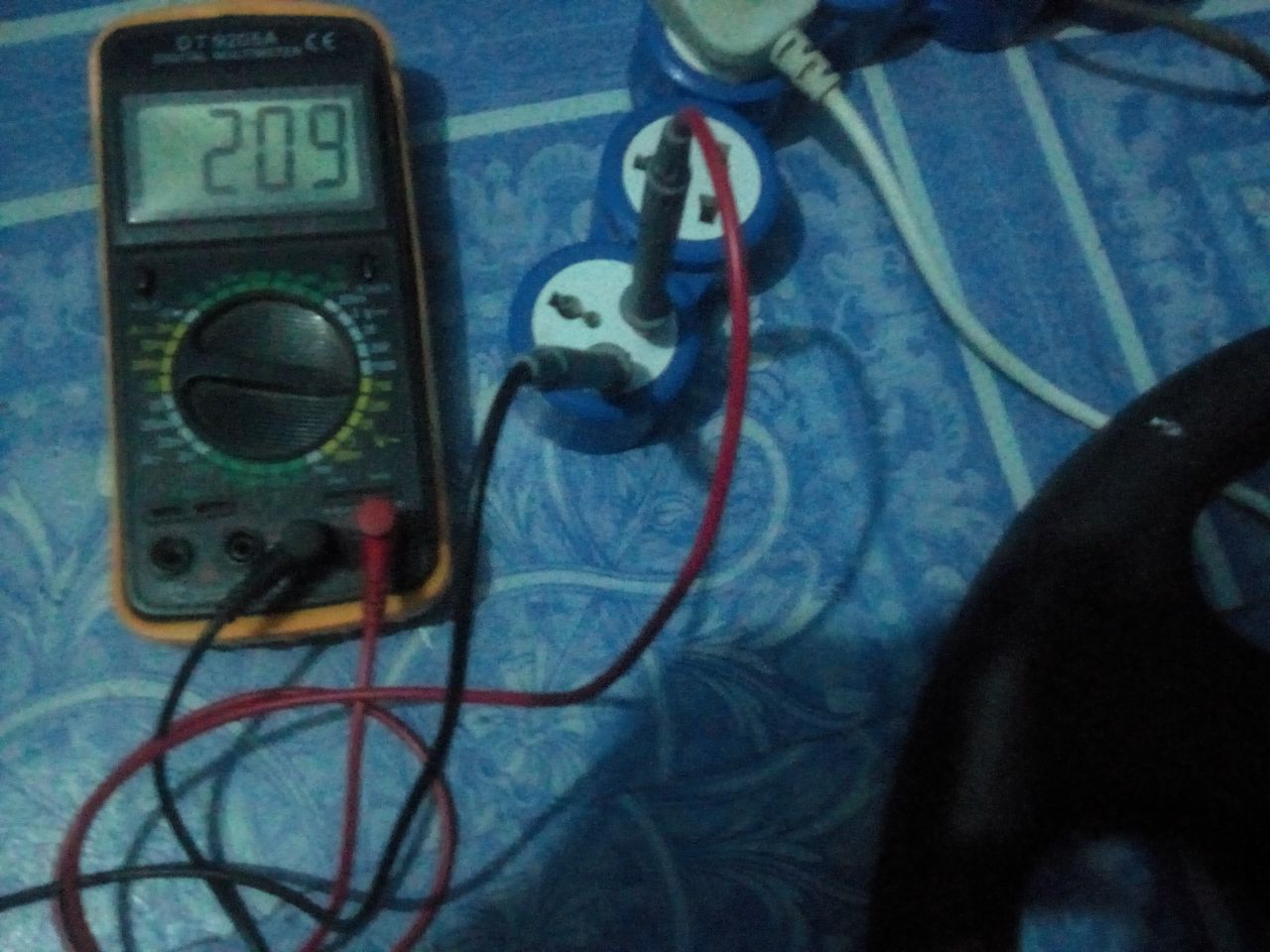
image credit: shut by me @ikchris
**Extra**: turning the knob to the voltage side converts the multimeter into voltmeter. Turning the knob connect a very high resistor in series with the internal resistance(resistance of the blue and orange coils) of the galvanometer.This allows only negligible current to flow. Thus measuring the potential difference between the two terminals
Measuring Resistance With The Multimeter
To turn your multimeter into ohmmeter, first switch on the meter and connect the probe wires. After follow the steps below**1**. Rotate the knob to the ohms(Ω) side. Depending on the resistance you want to measure: select 200Ω ohms if the resistance being measured is less than or equal to 200Ω; select 2KΩ if the resistance being measure is more than 200Ω but less than or equal to 2KΩ and so on.
*Am using Sanwa Digita Multimeter DT 9205A as refrence.*
**2**: Knit firmly the two probe wires on the two metallic terminals of the resistor
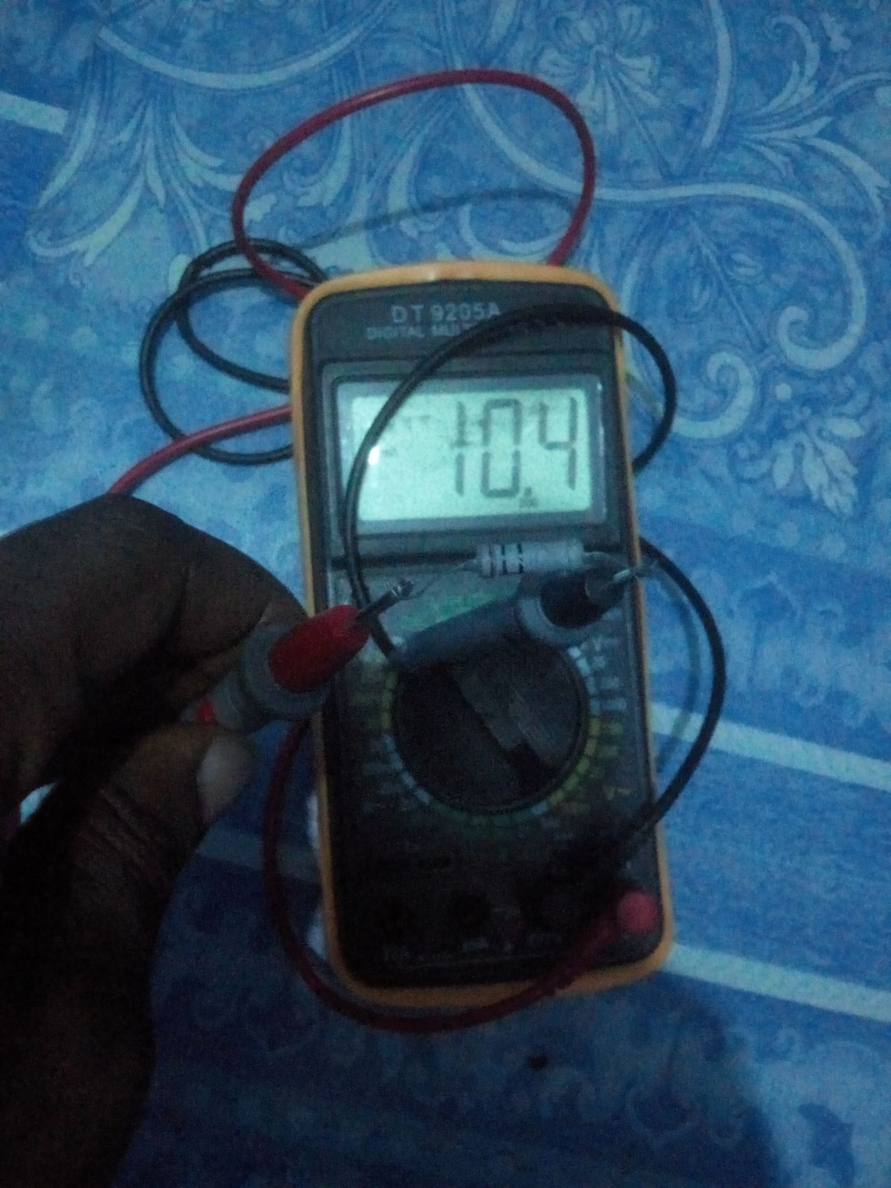
Image shut by me @ikchris
**3**: Record the display on the screen or read the scale.
**Quick Tip**: Some resistors has their resistance inscribed in their bodies why some use [colour codes](https://steemit.com/steemstem/@ikchris/understanding-resistor-colour-code-and-tolerance). It is usually four colour bands, five colour bands but rarely six colour bands.
**Extra**: Multimeter has a battery enclosed in it. While measuring resistance, it connects the resistance being measured in series with the internal resistance of the multimeter. As usual, any assembly of voltage source and resistance must produce current. However, there is a minimum current required by the multimeter to function which is provided by the battery. So in measuring resistance, some currents are passed from the battery to the resistance then voltage drop from the battery is measured and the corresponding resistance is displayed on the screen of scale. The lower the resistance, the higher the deflection for an analogue multimeter.
Measuring Current With The Multimeter
In measuring current, a series connection between the load, the meter and the voltage source is essential. To measure current with multimeter, follow the below steps:1. Connect the probe wires to the right channel. The black wire to the COM or Ground channel and the red wire to the 20A channel. *As a beginner, to avoid electric shock or electrocution, do not measure current if the voltage involved is of high magnitude*.
2. Turn the knob to the current side (A---), to measure direct current.
3. Connect your meter in series with the voltage source and load as shown in the image below. (I recommend you measure direct current from a battery to minimize the risk of electric shock)
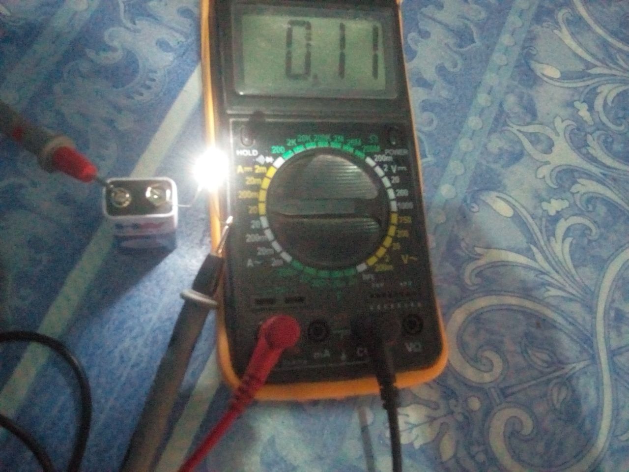
image credit: shut by me @ikchris
4. Record the value displayed on the screen or read the scale.
**Tip**: I used a white LED so you would understand better, using a resistor only, no indication to know if you connection is right or wrong.
In the image I used, I connected the positive terminal of the LED to the black probe, the negative terminal to the negative of the battery, then the red probe wire to the positive terminal of the battery. The current drawn by the LED from a 7V(it should be 9V but the battery is old) battery is 0.11A. if your connection is right, your LED must light.
**Images are attached to all the measurements to enhance understanding**
Conclusion
With the multimeter, you can measure current, resistance and voltage with just rotating the knob appropriately. There are different operationnal principles multimeter manufacturers use in designing a multimeter but the analysis i gave is the one commonly used(at least for multimeters seen here in Nigeria).References
* [Force in a current carrying conductor](https://www.miniphysics.com/force-on-current-carrying-conductor.html)* [Magnetic field due to a current carrying conductor](https://byjus.com/physics/magnetic-field-current-conductor/)
* [Hooke's law of elasticity in springs](https://www.britannica.com/science/Hookes-law)
* [The deflection of a galvanometer](https://en.wikipedia.org/wiki/Galvanometer)
* [Basics of the multimeter](https://en.wikipedia.org/wiki/Multimeter)
* [Converting a galvanometer to voltmeter](https://www.citycollegiate.com/galvanometer_XIIa.htm)
* [The working principle of the voltmeter](https://www.electrical4u.com/working-principle-of-voltmeter-and-types-of-voltmeter/)
* [The multimeter as an ohmmeter](http://www.idc-online.com/technical_references/pdfs/electrical_engineering/How_to_use_a_multimeter_as_Ohmmeter.pdf)
This post has been voted on by the SteemSTEM curation team and voting trail in collaboration with @utopian-io and @curie.
If you appreciate the work we are doing then consider voting all three projects for witness by selecting stem.witness, utopian-io and curie!
For additional information please join us on the SteemSTEM discord and to get to know the rest of the community!
Hi @ikchris!
Your post was upvoted by Utopian.io in cooperation with @steemstem - supporting knowledge, innovation and technological advancement on the Steem Blockchain.
Contribute to Open Source with utopian.io
Learn how to contribute on our website and join the new open source economy.
Want to chat? Join the Utopian Community on Discord https://discord.gg/h52nFrV
Congratulations @ikchris! You have completed the following achievement on the Steem blockchain and have been rewarded with new badge(s) :
Click here to view your Board
If you no longer want to receive notifications, reply to this comment with the word
STOPHello @ikchris! This is a friendly reminder that you have 3000 Partiko Points unclaimed in your Partiko account!
Partiko is a fast and beautiful mobile app for Steem, and it’s the most popular Steem mobile app out there! Download Partiko using the link below and login using SteemConnect to claim your 3000 Partiko points! You can easily convert them into Steem token!
https://partiko.app/referral/partiko