Pump and its classification
INTRODUCTION
A pump is a device which moves fluid through a piping system by mechanical action. It is a pressure (hydraulic) driven machine which converts mechanical energy to hydraulic energy. There are three classification of pumps according to method of transporting fluid. They are displacement pump, direct lift pump and gravity pump.
Pump operate by rotary and reciprocating mechanism and consume enegy in moving fluid. The source of energy for pump are electricity, wind power, manual operation.
Types of pump
- Positive displacement pump
- Non positive displacement pump
1. POSITIVE DISPLACEMENT PUMP
The positive displacement pump transports fluid by constraining a fixed volume and displacing that trapped volume in a discharge pipe.
It is divided into two types:
Rotary Positive-displacement pump.
Recipocating Positive-displacement pump.
Rotary Positive-displacement pump
Rotary positive displacement pump transports fluid by rotating mechanism that creates a space (vacuum) that captures and draw fluid into the pump.
It is classified into;
Gear pump: This is a simple rotary pump which operates by pushing transported fluid between two gears.
Rotary vane pump: these have a round and hollow rotor encased in a comparably formed lodging. As the rotor circles, the vanes trap liquid between the rotor and the packaging, drawing the liquid through the pump.
Screw pump: the state of the internals of this pump is generally two screws turning against each other to pump the fluid.
Reciprocating Positive-displacement pump
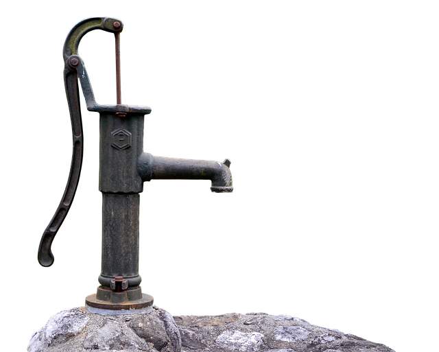
Reciprocating type Positive-displacement pump move the liquid utilizing at least one or more oscillating piston, plungers or diaphragms(membrane) , while valves confine liquid movement to the coveted course. This type of pump has one or more cylinder. The cylinders can either be single acting with suction in one direction of the piston movement and discharge on the other side or double-acting with suction and discharge in both directions.
The types of reciprocating pumps are:
- Plunger pump.
- Diaphragm pump.
- Piston displacement pump.
Plunger pump: A Plunger pump pushes the fluid through valves that are opened, closed by suction on way back.
Diaphragm pump: in this type of pump, a plunger pressurizes hydraulic oil which is used to flex the diaphragm in the pumping chamber(cylinder). Diaphragm pumps are used to pump toxic and hazardous fluids.
Piston displacement pump: these pump are usually very small and pumps and pumps liquid or gel manually.
2. NON POSITIVE DISPLACEMENT PUMP
In this pump category, the voltage of fluid pumped depends on the viscosity of flow. Resistance in a discharge(release) line creates force in opposite direction. When these forces are equal, the liquid will not flow.
If the outlet of the non positive displacement pump is closed, the release pressure will rise to maximum for a pump operating at highest speed.
Non positive displacement pump is classified into:
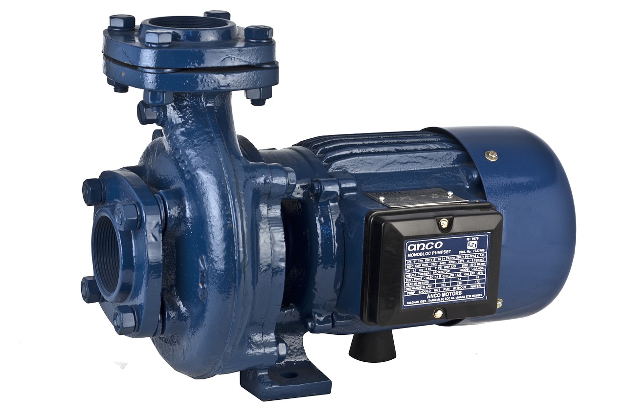
Centrifugal pump
Centrifugal pump is a rotodynamic pump that uses a pivoting impeller to expand the weight and flow rate of a liquid. Centrifugal pumps have most applications in moving fluid through pipes.
Submersible pump
Submersible pump is a device which has a hermetically fixed engine close-coupled to the pump body. The advantage this pump has over other pump is that elevation does not affect the flow of fluid. This is called pump cavitation. Submersible pump is more efficient than other pump type such as jet pump.
Working principles of submersible pump
The submersible pump usrd in ESP establishments are multistage radial draw working in a vertical position. Created fluids, in the wake of being subjected to awesome radial powers caused by the high rotational speed of the impeller, lose their motor vitality in the diffuser where a change of motor to weight vitality happens. This is the fundamental operational component of spiral and blended stream pumps.
The pump shaft is associated with the gas separator or the defender by a mechanical coupling at the base of the pump. The liquid enter the pump through an admission screen and are lifted by the pump stages. Different parts incorporate the spiral bearing (bushings) appropriated along the length of the pole
giving spiral help to the pump shaft running at high rotational velocities.
The blended stream pump are mostly made out of four subcomponents.
These subcomponents are the driver, discharge head, column assembly and the pump assembly. The power is transmitted from the electric engine or some other kind of driver, for example, diesel motor to the pump.
There are distinctive kinds of electric engines utilized as a part of various applications. On the off chance that the pump is driven from the best, the discharge head is utilized also, the column pipe and the middle shaft are balanced for the unique establishments. On the off chance that the length of the establishment is expanded, the quantity of the orientation used to hold the halfway shaft is likewise expanded.
In the applications where the driver is situated on the highest point of the discharge head, the power is transmitted to the pump by methods for a few
shaft associations. The motivation behind why a few shafts are utilized to transmit the control is the adaptability of the establishment. The head shaft experiencing the discharge head is set between the middle of the road shaft and engine. The
stuffing box is set the discharge head which is keeping the water originating from the section get together break into the engine side. The column assembly is made out of pipes which are associated with each other and the base end of the column assembly in the vertical bearing is associated with
the discharge portion of the pump. The intermediate shaft is situated in the column assembly and associated with the head shaft and direct shaft by methods for coupling associations.
However the halfway shaft is focused in the column assembly by methods for diary orientation. The separation between the direction are balanced
as per the rotational speed of the pump. The pump shaft holding the impeller is associated with the moderate shaft. The impellers are bolted on
the poles by methods for impeller bolt collets or key associations.
PUMP EFFICIENCY
Pump efficiency is defined as the proportion of the power bestowed on the liquid by the direct in connection to the power provided to drive the pump.
For centrifugal pump, efficiency increases with flow rate increase up to midpoint and it then starts to decline as flow rate increase further.
Generally, pump efficiency decrease overtime due to wear and tear.
Power output from pump
The hydraulic horsepower of pump is determined by discharge and suction pressure. It is given by
Power Output from Pump = (P2–P1) * Q
P2: Pump Discharge pressure in N/m2
P1: Pump suction pressure in N/m2
Q: Flow delivered by pump in m3/s
REFERENCE
- wikipedia
- Lecture note
- eit.edu.au
- academia
All images are Creative Commons or public domain, no copyright infringements have occurred.

I had trouble visualizing how all these pumps work. Incredibly smart designs!
Nice work..I earlier spoke on the invaluable importance of this machine...Thanks for again buttressing it...
You could have spaced the work well though...u can easily use
between the paragraphs
Pumps are mechanical devices used to transfer fluids from one place to another. They play a crucial role in various industries, including manufacturing, construction, and agriculture. Also, you can visit https://www.smartnewo.com/ and gain the best pump information. Pumps can be classified into different categories based on their design and application. Common classifications include centrifugal pumps, positive displacement pumps, and reciprocating pumps. Each type has its unique characteristics and is suited for specific fluid transfer requirements.