Experimental determination of the relationship charge electron mass
Hello friends of steemit lovers of science today I want to share a very simple experiment that is used a lot in the subjects taught in the undergraduate physics, something elementary for every student of physics.
I hope you like it.
The use of Helmholtz coils gives us an important tool when obtaining controlled situations in order to verify an influential phenomenon in charged particles, because with them it is possible to generate uniform magnetic fields in a region of space. In the present investigation, this instrument is used in order to experimentally verify an important value within the world of physics, as is the charge-mass ratio of the electron. Initially this experiment devised by JJ Thompson for the late nineteenth century, is basically about heating a filament of the metal that at the time emits electrons, which by means of a magnetic field generated by coils are accelerated by describing measurable circular trajectories, which change in function of the voltage or current supplied. Thus, taking a record of the variation of the radius as a function of the voltage or applied current, this relation can be experimentally shown.
The British scientist J.J Thompson is known in large part thanks to his efforts to study the phenomena produced by charged particles in his famous cathode ray tube. Through this he was able to show that the rays emanating from a metallic filament at high temperatures could be deflected in the presence of a magnetic field, being possible to measure this deviation and demonstrate a constant relationship that these particles possess, the charge-mass ratio. (e / m). In the same way I can show that this behavior occurs in any material used as a cathode, thus being this particle charged to any material. relation can be experimentally shown.
His experiment is based on the fact that the electrons are emitted by a cathode at a negative potential with respect to the anode, which originates an electric field accelerator of electrons, through which the electrons are directed to a region between the plates of a capacitor where it is produced an electric field perpendicular to its direction, whereby they are accelerated vertically by striking a fluorescent screen at the end of the tube, registering a displacement d with respect to its initial trajectory. The following illustrates this phenomenon.
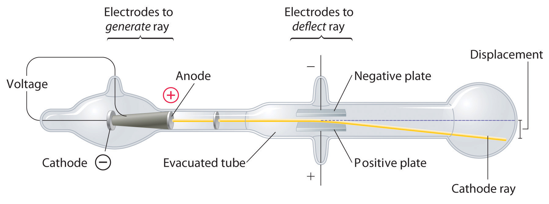
Figure 1. Illustrated model of the thompson experiment.
Source
The physical analysis of this phenomenon is obtained by studying the case of an electron that moves with constant velocity and in the presence of a magnetic field B perpendicular to the direction of v, thus the force applied to the electron due to the presence of a magnetic field It is given by:
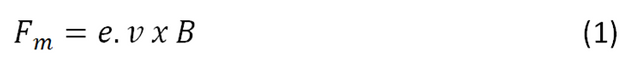
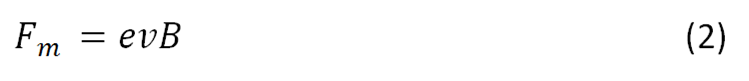
Where e is the charge of the particle in motion. However, if the incidence is perpendicular the equation reduces to:
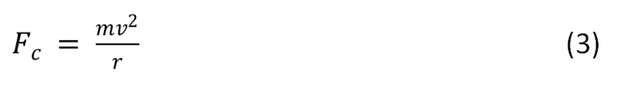
When this force acts on a flow of electrons in the presence of a constant magnetic field created by Helmholtz coils, they describe a circular path so that in this case the magnetic force can be described as centripeda governed by the equation.
So that equating equations (2) and (3) we obtain a charge-mass relationship given by:
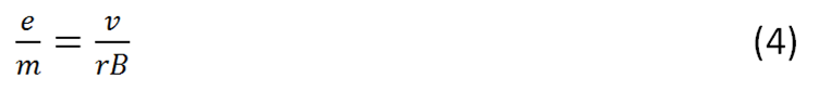
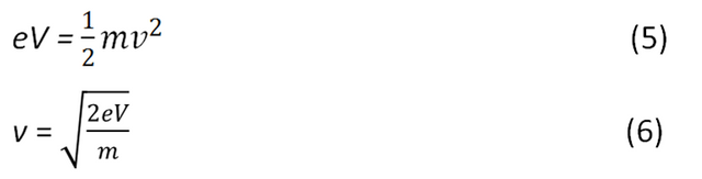
Thus, we have this relation in dependence on the velocity v of the particle, the radius r described in its trajectory and the magnetic field _B- to which it is subjected. Because the electrons are subjected to an electrostatic poptencial, this means that their kinetic energy is given in its entirety by the potential applied to the electrons, so we have to:
It is also known the magnetic field generated by the Helmholtz coils in the vicinity of its center, by means of the Biot-Savart law applied to this coil arrangement it is demonstrated that:
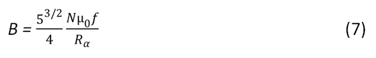
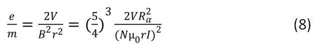
Knowing the fact that this type of coils have a constant magnetic field N as the number of turns of the coil (N = 130), **Rα- as the radius of the coils _(R_α = 15cm_), I is the intensity of the current that circulates through the rings and _μ0** the magnetic permeability of the vacuum _(μ_0 = 4pi. 〖10〗 ^ (- 7) NA ^ (- 2))_ substituting (6) and (7) into (4) we obtain:
A tube to lower pressure with He at a pressure of 〖10〗 ^ 2mmHg. Where is the electron accelerator cannon. Its function is to contain the pressurized gas with the electrons interacting emitting light.
An electron gun that emits a thin beam when heating its cathode. Here the electrons are accelerated by the applied potential between the anode and the cathode. Vmax = 6.3V.
A pair of Helmholtz coils for the purpose of generating a uniform magnetic field inside the tube pressurized with He gas.
A cloth hood that is placed over the device in order to isolate it from external light so that the electron beam generated inside the tube is visualized.
A mirror with metric scale where the variation of the radius of the circumference described by the electron beam is observed.
A control role of the device where all the connections to be made are explicitly located.
Banana-banana cables to make the connections.
Two sources of tension: one with capacity to generate 6V-9V and another to generate voltages of 150V-400V, with an output of up to 6.3V.
A voltmeter and ammeter.
To carry out the experiment, the variation of the radius that forms the circumference is measured as an indirect measure to calculate the charge-mass ratio of the electron, these are made visible by the emission of photons after their interaction with the gas inside the tube. The experiment consists of two stages:
The first is to leave the current fixed and vary the voltage, taking note of the variations of the ratios.
A second phase consists in fixing a voltage varying the current and in the same way registering the variation of the radius of the circumference that describes the electron beam. To carry out the relevant connections, proceed according to the figure shown below:
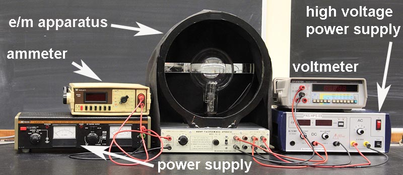
Figure 2. Representative diagram of the assembly of the experiment.
Source
Once the assembly is done, verify that the circumference described by the electron beam is aligned, and then proceed to take the corresponding measurements according to the phase of the experiment.
For the first experience, keeping the voltage constant (V = 207). We proceed to measure the variation of the radius of the beam circumference as a function of the current supplied, and by means of equation (8) the charge-mass relation is determined for this part of the experiment. The results are shown in table 1.
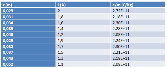
Table 1. Results obtained from (e / m) V = ctte.
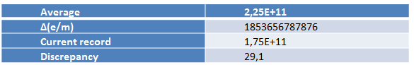
Table 2. Final results obtained from (e / m) V = ctte.
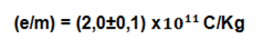
In this case we see that the value of the load-mass relation is obtained as follows:

Presenting a discrepancy with respect to the current record of 29%, and an error in the measurement of 8.21%.
Next, the results obtained for the second experience are obtained in the same way, in which a constant current is maintained and the variation of the radius of the circumference described by the electron beam as a function of the voltage supplied is studied. Here we have that for the fixed current I = 1.5 A. The results are shown in the following table.
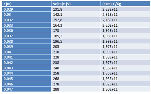
Table 3. Results obtained from (e / m) with I = ctte.

Table 4. Final results obtained from (e / m) with I = ctte.
Here we see that the value of the load-mass ratio is obtained as follows:
Presenting a discrepancy with respect to the current record of 16.19%, and an error in the measurement of 6.59%.
At the end of the proposed practice it is concluded that this important physical constant is verified in a good way, experimentally obtaining a value for the load-mass relation according to each proposed experience, however, there are marked errors and at the moment of making conclusions about it, it is worth highlighting which are the product of systematic errors concerning the technique used to collect data in each experience, but it is also noteworthy that through this research a clear and simple experimental method for the determination of this physical constant is presented. can be optimized by improving the technique used to take data, taking a good range of measurement and it is very important to verify before making measurements the correct connection of the instruments used, having knowledge of the precautions that the manufacturer of the equipment warns and thus avoid damages in the same.
"Electron charge / mass ratio", available in: https://www.ugr.es/amaro/lfc/guiones.pdf
Johannes Rech "Physical EB scientific" available in: http://www.3bscientific.es/medialibrary/downloads/fisica_es_2012.pdf
http://demoweb.physics.ucla.edu/content/experiment-6-charge-mass-ratio-electron
Instruction Manual and Experiment guide for the PASCO scientific. Model SE-9368
Congratulations @carloserp-2000! You have completed some achievement on Steemit and have been rewarded with new badge(s) :
Click on any badge to view your own Board of Honor on SteemitBoard.
For more information about SteemitBoard, click here
If you no longer want to receive notifications, reply to this comment with the word
STOPimg credz: pixabay.com
Nice, you got a 54.0% @adept upgoat, thanks to @carloserp-2000
It consists of $1.06 vote and $0.35 curation
Want a boost? Minnowbooster's got your back!
The @OriginalWorks bot has determined this post by @carloserp-2000 to be original material and upvoted(1.5%) it!
To call @OriginalWorks, simply reply to any post with @originalworks or !originalworks in your message!