The Math behind Low-Pass Electronic Filters: Application of First Order ODEs
Consider a simple electric circuit consisting of a power source, a resistor (R = 15Ω) and an inductor (L = 3H).
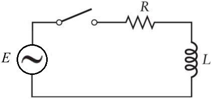
This is commonly known as an RL series circuit. Such circuits are often used as low-pass electronic filters. That is, they allowing the passage of low frequency signals through the inductor to the output, whilst restricting high frequency signals.
Let's assume that when the switch is closed, the power source produces a sinusoidal voltage and current (i.e. AC) that flows through the circuit according to the following equation...
The voltage drop across the resistor is given by Ohm's law. That is...

The voltage drop across the inductor is given by the inductance L by the rate of change of current dI/dt.

According to Kirchoff's Voltage Law (KVL), the voltage drop around any closed circuit is equal to the supplied voltage. Thus...

Equation (1) is a first-order, linear, nonhomogeneous differential equation of the form...

...for which we can solve by multiplying equation (2) by an integrating factor...

So in our case, P(x) = R/L, so our integrating factor is...

Now, multiplying the entirety of equation (1) by the integrating factor F gives us...

Notice that the left-hand side of equation (3) is the product rule expansion (i.e. the derivative) of IeR/Lt. So, equation (3) can be simplified to...

Ok. Now we can integrate both sides of equation (4)...

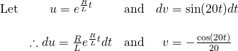
The integral on the right-hand side of equation (5) can be evaluated via integration by parts...
Hold on, because this is going to be fairly ugly!
So for...

Thus...

Now, for the trailing integral in equation (6), we need to apply integration by parts yet again...

And thus...

Now substituting the above result back in to equation (6), we get...

Now we have matching in integrals on both sides of equation (7). The trailing integral on the right-hand side of equation (7) we can move over to the left-hand side...

Don't worry. I had a real hard time keeping track of this too. So if you didn't get it the first time, run through it again and take your time. But now that we have a result for the integral, we can substitute it back into equation (5) to finalise our solution
So...

We're nearly there. Now substituting known values of resistance and inductance into equation (8), we get...

Finally, we need the initial value of current I to determine the constant of integration C. At time t = 0, the voltage from the power source E(0) is 0, therefore the current in the circuit is also 0.

A graph of the particular solution for current in the circuit I at time t is shown below...

All equations in this tutorial were created with QuickLatex
All graphs are created with www.desmos.com/calculator
First & Second Order Linear ODE's and their applications
- An Application of First Order ODEs: The RL Circuit
Please give me an Upvote and Resteem if you have found this tutorial helpful.
Please ask me a maths question by commenting below and I will try to help you in future videos.
I would really appreciate any small donation which will help me to help more math students of the world.
Tip me some DogeCoin: A4f3URZSWDoJCkWhVttbR3RjGHRSuLpaP3
Tip me at PayPal: https://paypal.me/MasterWu
@originalworks
You got a 0.91% upvote from @upmewhale courtesy of @masterwu!
This post has received a 2.82% upvote from @msp-bidbot thanks to: @masterwu. Delegate SP to this public bot and get paid daily: 50SP, 100SP, 250SP, 500SP, 1000SP, 5000SP Don't delegate so much that you have less than 50SP left on your account.
You got upvoted from @adriatik bot! Thank you to you for using our service. We really hope this will hope to promote your quality content!