A detailed look at my Solar System setup
A detailed look at my Solar System setup
In this post I will give a more detailed description of how my solar system is all connected together
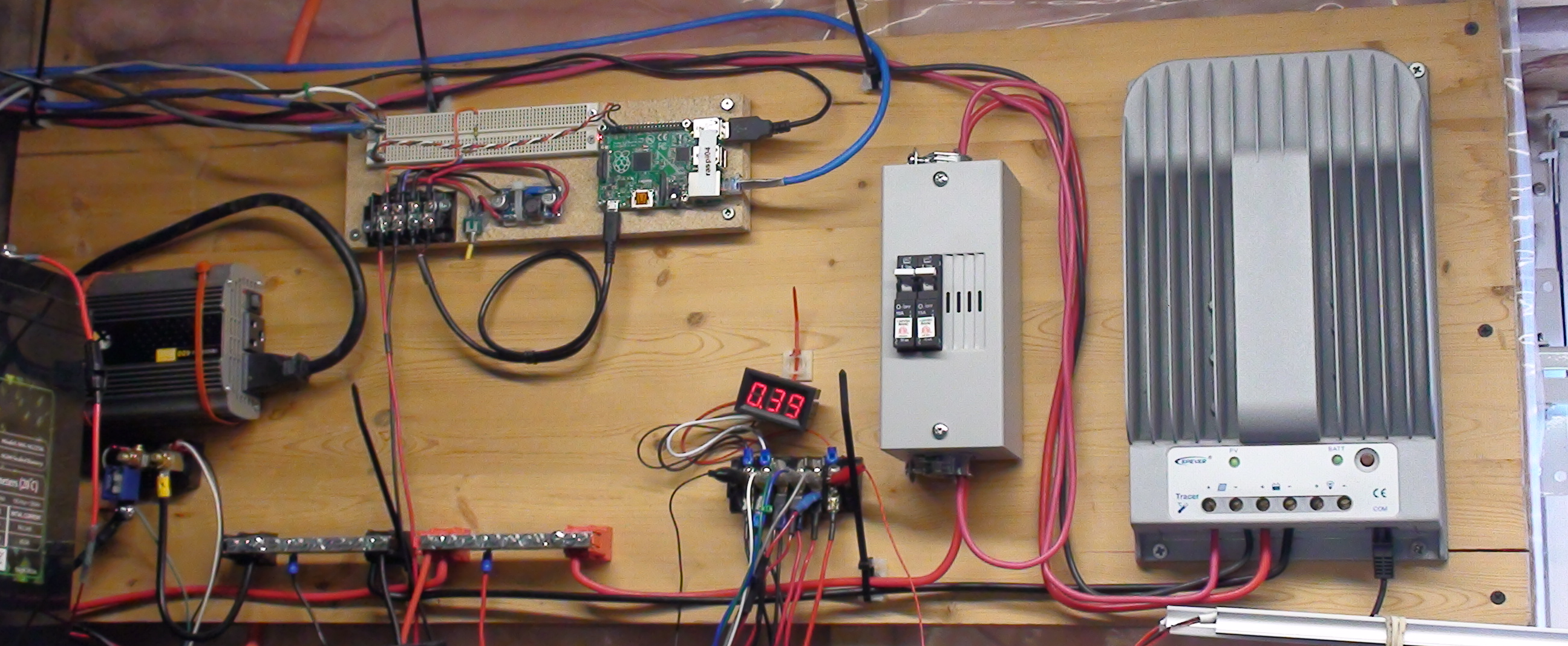
Wiring panel where all the magic happens
As you can see there are quite a number of components involved with making all this work. The Raspberry Pi mounted on the wood block is actually not part of the solar system. I will now work through how the pieces connect together.
Solar Panel
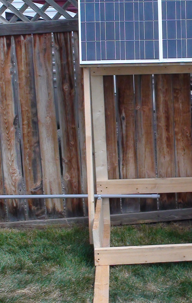
Here is a picture showing a part of the solar panel rack. Unfortunately the wires have not been installed yet. The plastic pipe that is on the lower left of the picture goes from this rack to a hole drilled into the foundation of my house.
The pipe starts out in the open and as the ground slopes it gets buried as it gets closer to the house. This pipe currently has three wires pulled through it. Two 10ga wires, one red and one black. These wires are exterior rated solar cable and are the DC voltage from the solar panels. The third wire is a Cat 5 network cable which I use to monitor the temperature at the back of the solar panels.
As I currently have two 80Watt solar panels connected in series the voltage produced should not exceed 42.6 Volts and 5.3 Amps. These are the Open/Short circuit measurement of the two panels connected in series. Connecting the panels in series increases the voltage and keeps the current down which is more efficient and allows for smaller gauge wires.
Breaker Panel
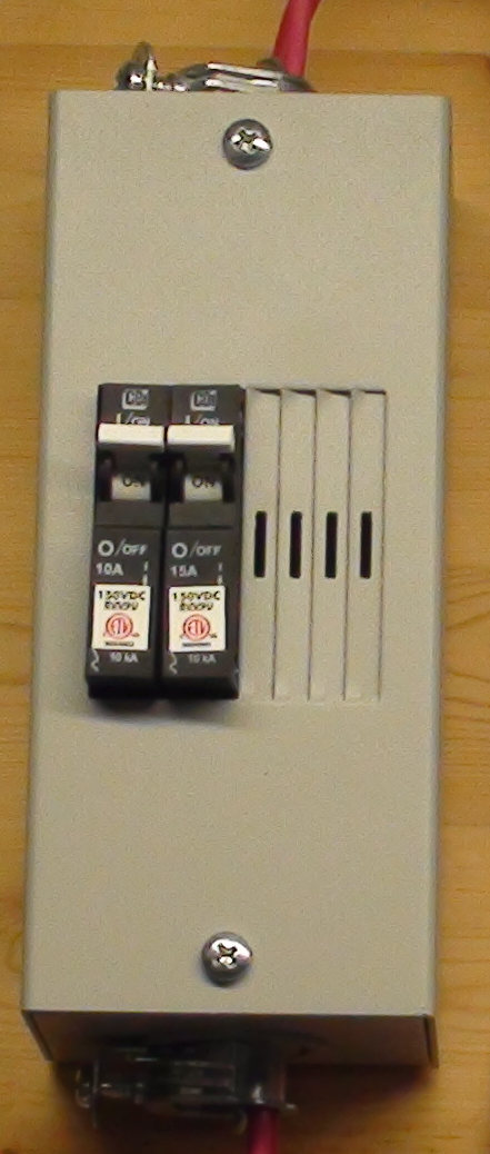
Here is a close up picture of my solar breaker panel. This panel has breakers for both solar power into the charge controller and the power out to the batteries.
After the wires enter the house the black (negative) goes directly to the charge controller, but the red (positive) goes into the left breaker. The right breaker is for the output of the charge controller.
Charge Controller
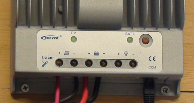
I am currently using a Tracer 4215BN MPPT charge controller. This picture just shows the bottom of the controller where the wires connect.
A MPPT (maximum power point tracking) charge controller is able to adjust the load on the solar panels to get the best amount of power from the panels and then into the battery bank. The charge controller is programmed with the type of batteries and knows what the specific charge needs of the battery are. I am not able to properly describe this operation as there are a lot better resources on-line.
I bought this controller with expansion in mind. I can upgrade my system to three 300Watt panels and a 24V battery bank. At that time I might need to upgrade the breakers and/or internal panel wiring.
As you can see there are five wires connecting to the bottom of the charge controller. The two on the left are power coming from the solar panels (thru breaker). The two wires in the middle are power going to the main buss bars (thru breaker). The third wire is a RS485 communications cable for monitoring the charge controller. It is also used to manage the charge setting of the controller. This cable is connected through a RS485 to serial adapter which is connected to one of my Raspberry Pi computers.
Main Buss Bars
The main buss bars are for distributing the battery bank power.
The main buss is where any higher current devices connect to the battery bank. The large red and black wires on the right side of the buss are the power from the charge controller. The large red and black wires on the left are the power going to the battery bank. The black wire goes through a fused current shunt described below. The two medium sized red and black wired connect to my inverter also described below.
Current Shunt
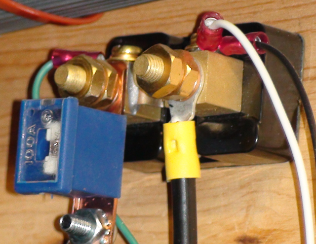
The fused current shunt shown below connects the negative buss bar to the battery bank.
The black plastic block with the two large terminal posts is the actual shunt and the blue plastic box is a 100Amp fuse. Safety first. The smaller wires are used to monitor the amount of current flowing into or out of the battery bank.
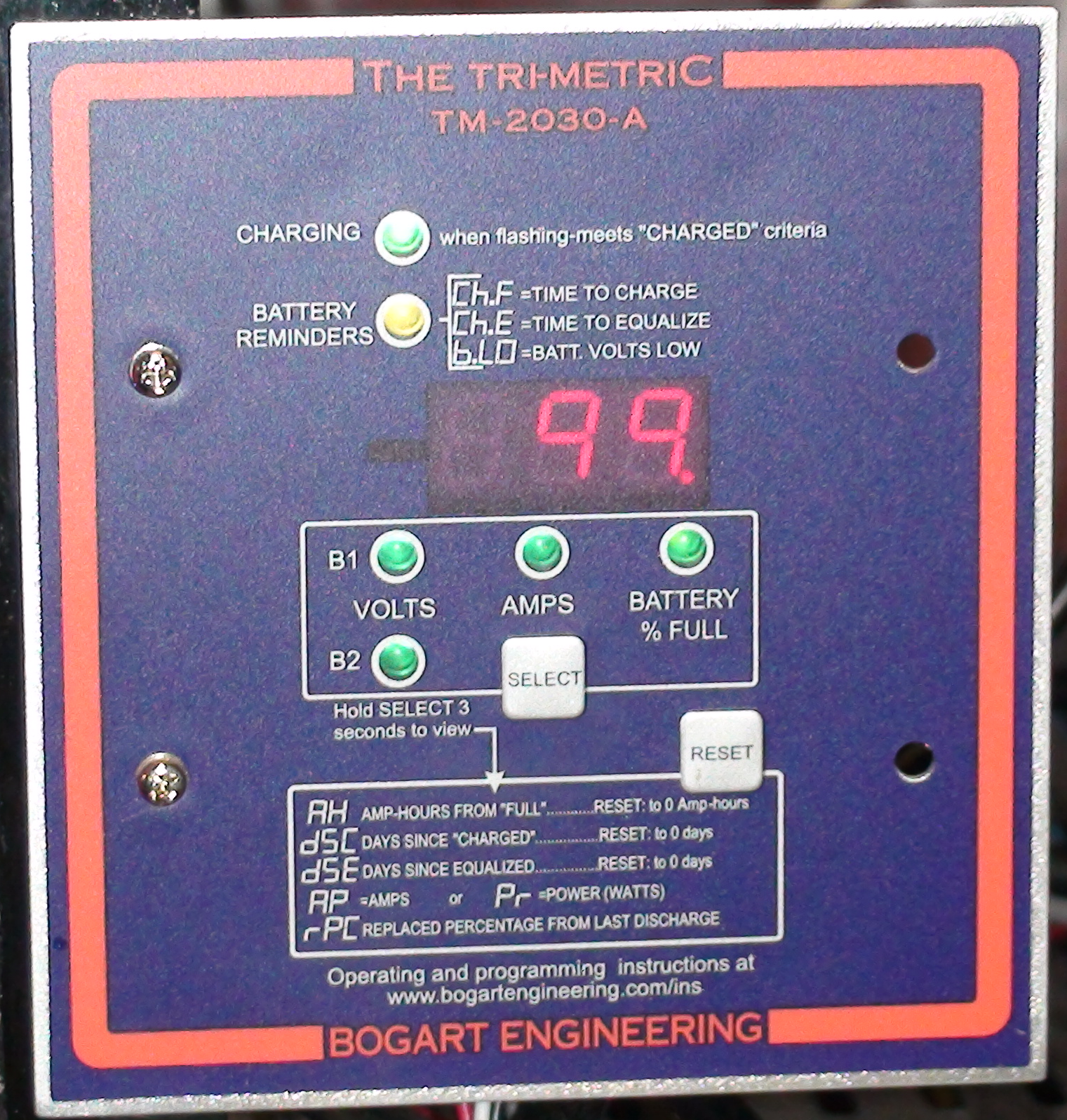
Below is the Tri-meteric TM-2030A device.
This device is connected to the current shunt and allows you to manually monitor the battery bank State of Charge and Voltage. The SOC is calculated by using the battery voltage as well as the current into and out of the battery bank. One nice feature of the device is it has a serial data port which outputs a 2400baud data stream. I currently have this connected to another one of my Raspberry Pi computers. I am only logging the data stream to a text file until I learn enough Python to be able to read the data stream and then log it to a database.
12V Buss
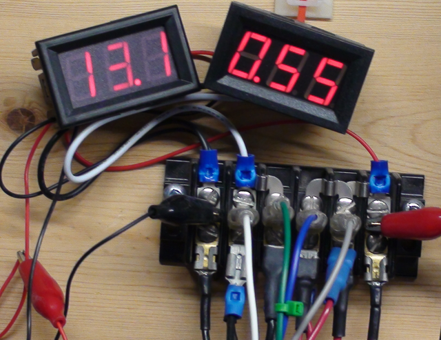
Here is a picture of my 12 volt buss.
This buss is where I currently connect any devices wanting 12 Volts. The link between this buss and the main buss also has an in-line fuse.
I have several step down converters for running my Raspberry Pi computers and one step down converter connected to a 5volt USB hub which I use to charge my cellphone and ebook readers. I have several other 12V devices like a 18650 battery charger connected to the 12V buss.
In the future when I upgrade the battery bank to 24V I have a 24 to 12V converter that will step down the battery bank voltage to 12 volts and I will not have to worry about and of the devices connected to the 12V buss.
12v DC to 120v AC inverter
This picture is of my 500Watt inverter.
This inverter was given to me and is part of the reason I am currently running a 12V battery bank. Is is a Modified Sine Wave inverter. Modified sine inverters do not output a true sine wave so not all AC devices will run correctly. I am currently not running the inverter as I do not have enough power to run any devices full time. I have run a small desktop computer for several hours from it before.
The Future
Like all DIY people in working with solar systems I will be upgrading my solar system. I follow a number of people on YouTube who do solar and the only constant for DIY solar is CHANGE. If one has a large chunk of money one can build out a solar system fully capable of running your whole house, I do not.
My first upgrade short term will be to take an old 24V UPS and turn it into my inverter. Thankfully it outputs Pure Sine AC and is capable of outputting 1000Watts. I could then run my lighting in the Man Cave as well as other AC devices when the rest of the system capabilities grow.
The second upgrade will be two 250 or 300 Watt panels for quicker charging and the ability to run higher power devices during the day when the sun is out.
I have left out the details of how the batteries are wired, If anyone is interested I can take some more photo's and do up a separate post.


Great work wanted to see the finished product
LOL, it will never be finished, like I said DIY solar never seems to stop changing. Always one more upgrade...
I've always loved clean energy and solar seems to be the easiest for the everyday person. If solar panels ever got to the point where they are stronger, easier to install, and don't require a ton to charge up a Tesla(that I hope to get as well) I will be buying them.
Bam! I up-voted it using python in Linux, is the first time I do it. I feel proud of it LOL
And nice job with the solar system so far, by the way haha.
It will keep me out of trouble posting the upgrades and the Raspberry Pi - Python monitoring.
Do you have post where you show the code on how you did that?
No, I found an account of some guys that post tutorials. @steempytutorials check it up if you're interested. They say there that they do coding contests as well, I'll go slowly trough the tutorials.
Thanks I will check that out as well.
Congratulations! This post has been upvoted by SteemMakers. We are a community based project that aims to support makers and DIYers on the blockchain in every way possible. Find out more about us on our website: www.steemmakers.com.
If you like our work, please consider upvoting this comment to support the growth of our community. Thank you.
I have always built my own controllers, but this looks interesting. I must have the RS485 so the individual battery banks can report, and be under control. One of these on each bank might fill the bill. I have several hundred left over Pic processors, but haven't started that yet, so I will look at these processors first.
Are you saying that you built your own charge controller? Do you not currently have shunts for monitoring?
Sorry, I was not clear. The solar charge controllers are cheap, using several of those. I am building a power bank, that is composed of multiple sets of LiIon batteries (24 volt) in parallel. I will have a resistor under the cathode side of each battery stick, with a Tmos power FET switching ground under processor control. This will allow me to set the current each stick provides. If a stick drops voltage (bad cell) I will turn it off, and signal the failure. Then I can pull it, and repair it. With 350 sticks, a battery problem will not affect the available power. I will build 30 sticks in a 5 gallon bucket, buried in the ground to cool them. Each bucket will provide 1800 watts to the buss, through shottkey diodes (to reduce the diode losses). That is why I need the RS485, so I can poll single buckets. The controller I was talking about would be a simple SBC to controll the Tmos Power FETs; I/O is the problem, I need 30 analog inputs, and 30 digital outputs that I can PWM, per bucket. It looks like this SBC has 40 general I/Os to begin with, it might be eaasier to add some I/O instead of scratch building the whole thing. Might even need to look at a PC-104 brick to get the hoursepower I may need. I can just plug in the needed expansion onto the top of that unit.
BUT, once done, I will have batteries that are rated for 15,000 full cycles, that are repairable as needed.
At 0.05 ohm shunt I will waste .31 watt at full power. and the feedback voltage will be 0.125 volts. The MTP 3055E Tmos power FET will drive directly from the processor Output. I may need a better FET, but will test first; the Rds on is 0.15 ohms, so the FET will disapate 0.94 watts (1.5% of the total switched power). A MTW45N10E will only waste 0.188 watts when switching, looks like a better choice to me. That will be 65 watts lost to switch 21000, and with the sensor loss total control cost is under 200 watts. Not sure if I wll need to amplify the 0125 Vdc, until I see how good the analog inputs are.
Wow, I think I understand most of that. You should do a post with pictures.
Instead of doing a standard power wall, with hundreds of batteries in parallel where I can not see a single battery if it goes bad, I am making a stack of cells that will give me 24 volts (at 60 watts), and combining them through a special (shottkey) diode bank that has lower losses. This way, if I loose a cell, I loose 60 total watts, when I turn it off, with a very low risk of auto ignition. If the auto Ignition occurs in a normal power wall, the offending battery can not be isolated, and the adjacent cells provide the power to ignite, then they ignite from the heat...Poof, all gone.
In my battery, if one does burn, the surrounding plastic tube melts and allows water to enter. Water will not extiguish the fire, as it provides its own oxidizer, but it will lower the temperature below the level needed to sustain the fire. Since the battery (5 gallon bucket) is buried in the ground, and not in my house, my house is not burned down. With about 350 of the battery sticks, I get the needed power from the parallel of these sticks. This also lets me limit the current supplied from each battery stick, which will give me the longest possible cycle life.
The last paragraph above is the power cost of using these controls. The FET acts kind of like a relay, and closes (Drain to Source) when a signal is applied to the gate, except it works VERY fast. That way, I can regulate the amount power allowed to flow, by turning them off and on very quickly (70,000 times per second). By leaving them on, more that the time they are off, the output is increased. This is called Pulse Width Modulation (PWM) and is so useful that most processors include the function.
I really like this post on the rasberry pi, with python software. It may save me a lot of design work on the processor control setup. Since I can't afford to pay myself for the work, this may be a good route, LOL!