Course "Electronics for all - Basic concepts of electrical circuits"
Electronics for everyone
Upon completion, the participant will have the basic knowledge of analog electronics, such as basic circuit design, circuit operation analysis, fault detection, equipment repair and maintenance.

Index
| Content | Post |
|---|---|
| Fundamentals of Electricity | Course "Electronics for all - Fundamentals of Electricity" |

Hello my dear Steemians! In this post we are going to talk about electrical circuits and the elements that comprise it.
What is an electrical circuit?
An electric circuit is a combination of components connected together in a manner that provides one or more closed paths that allow the circulation of the current and the use thereof for the performance of useful work.
Every circuit, however simple it may seem, has three important characteristics:
- It has a voltage source; without it, a current flow can not be established.
- There is a closed path, through which the current flows from one end of the voltage source to the other, passing through the external circuit.
- The path through which the current circulates, presents some opposition to its passage.
Electrical and electronic circuits, although they can be physically formed by a large number of components, which makes them look very complex, are all composed of three basic elements: a voltage source, a load and the electrical conductors.
Voltage source
It provides the necessary force to drive a stream of electrons through the circuits. This force is called voltage
The voltage
Voltage is the force that generates a flow of current through a circuit, that is, it is responsible for moving the free electrons that are in a circuit.
The symbols used to represent and the types of common sources are the following:

The voltages in a circuit are designed in several ways , like this:
- The voltage between the terminals of the power supply, is called electromotive force (FEM)
- The voltage between the terminals of a load, called voltage drop.
- The voltage between the two points automatically of a circuit, is called potential difference.
The voltage applied to the circuits can be basically in two ways:
If the electrons are always propelled in the same direction, that is to say, that the source always conserves the same polarity, the voltage in continuous (VCC).
If the electrons are driven first in one direction and then in the other continuously alternating the direction of the force, that is, changing alternately polarity, the voltage is alternating (VCA).
Unit of measurement
The unit used to measure the work done by the source when moving the electrons is called the volt (V). The number of volts represents the amount of force applied to a circuit. Electricity and electronics handle voltages greater than and less than the volt, which is why units of secondary measures called multiples and submultiples are used.
- The multiples are units greater than the fundamental unit.
- Submultiples, are units of measurement smaller than the fundamental unit.
| Prefix | Symbol | Multiplication factor | |
|---|---|---|---|
| Multiples | Kilovoltio | KV | x1,000 |
| Megavolt | MV | x1,000,000 | |
| Basic unit | Voltio | V | x1 |
| Submultiples | millivolt | mV | x0.001 |
| microvolt | μV | x0.000001 |
How is it measured?
The instrument used to measure the voltage is called a voltmeter. This must be connected in parallel with the element on which you want to take the measurement.

When using this instrument it is necessary to take into account its polarity and select a range of scale higher than the maximum voltage that you want to measure.

The charge
The charge converts the energy of electrons into motion, in electrical signals and other forms of energy.
The symbols used to represent some common types of cargo such as a resistance, a lamp, a motor or a speaker, son:

When current is flowing through a material it is hot, which shows that the applied voltage does a job to move electrons against some opposition. This opposition to the passage of current is called resistance.
The Conductors
The conductors are responsible for providing an easy or low resistance road for the circulation of the current. This group includes all the materials in which the electric current passes with great ease, such as metals and water, among others.
On the contrary, there is another type of material that offers a lot of opposition to the passage of the current and is used to isolate the passage of them. They are called bad conductors or insulators. Glass, ceramics, plastics in general are insulating materials.
Most used conductors
As we saw, the best drivers that have the orbit of Valencia have less than four electrons, such as copper, gold, silver and aluminum.

Resistance
All conductive or insulating materials offer some opposition to the passage of current, this is known as resistance. Therefore, resistance is defined as the degree of opposition offered by a material to the passage of electric current.
Unit of measurement
The unit used to measure the resistance of the materials is called ohm and is represented by the Greek letter omega (Ω). The number of ohms represents the amount of opposition that a material presents to the passage of the current. The higher the number of Ohms, the greater the degree of opposition to the passage of the current and, therefore, there will be less current.
| Prefix | Symbol | Multiplication factor | |
|---|---|---|---|
| Multiples | Megaohm | MΩ | x1,000,000 |
| Kilohmio | KΩ | x1,000 | |
| Basic unit | Ohmio | Ω | x1 |
With what are they measured?
Resistors are measured with an instrument called ohmmeter, which must be connected to the resistance that you want to measure regardless of the polarity.
We must never measure the resistance in a circuit through which the current flows.
Open circuit
For there to be current flow in the circuit, it is essential that there is a closed path. When any part of the trajectory opens, it is said that the circuit is open and there is no continuity in the conduction path and, therefore, the flow of electrons stops. The resistance of an open circuit is infinitely high.
An open circuit can produce by a loose connection, because the resistance of the burned load, by poorly made connections, by loose contacts or breaks in the conductor. If protection mechanisms are used, these are burned.


Short circuit
We already saw how an open circuit prevents the flow of electrons, now let's study the opposite, short circuits. In this case, there is a closed path between the terminals of the source, but the resistance of this path is practically equal to zero, which causes a flow of current higher than normal to circulate. In general, the short circuit occurs when a cable is installed between the edges of the load, when it is connected to the bare conductors or when they are connected directly to the terminals of the source.
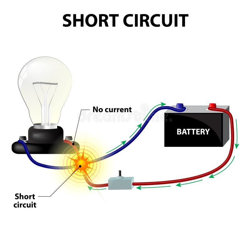
What can happen if a short circuit is caused?
When the current is increased excessively, a heating of the conductors that deteriorate the insulation and produce sparks that can cause fires and equipment damage occurs in the circuit. To prevent this from happening, use devices that protect against excessive current flow, called fuses.
Electric current
As we know, the electron is the basic unit of electricity, but because its charge is very small, it must move millions of them to produce an appreciable current. Since this number was too large to be expressed in words, a more practical unit called Coulomb (C) was created. The Coulomb represents the number of electrons that have been resting or moving through a conductor.
Intensity of electric current
It is the amount of electrons that pass or circulate through a conductor in a certain unit of time. It is represented by an arrow and measured in amperes (A).
It is important to know that the current always starts from the negative pole of the battery, circulates through the external circuit and goes back into the source through the positive pole.
Unit of measurement
The fundamental unit of the current in the ampere (A). However, in electronic circuits currents less than one ampere are handled in which case another unit called milliampere (mA) is used. For smaller currents the microampere (μA) is used.
| Prefix | Symbol | Multiplication factor | |
|---|---|---|---|
| Basic unit | Ampere | A | x1 |
| Submultiples | milliamperio | mA | x0.001 |
| microampere | μA | x0.000001 |
¿How the current is measured?
The intensity of the current through a circuit is measured with an instrument called an ammeter. To connect the instrument, keep in mind that the ammeter always connects in series with the line that supplies current to the circuit. As you can see in the following circuits.

In this way we force the circulation of the current through the ammeter and we make sure that the measurement is correct.
Let's study the circuit of the bulb, the circuit is formed by the conductors, this is the medium through which circulates the current that transports the energy from the voltage source to the filament of the bulb, where it is used to do a job, specifically generate light or heat. The resistance of the focus will determine the current that the source will supply to the circuit.


"The human being is intelligent by nature, technology is only a complement"
╭════════════╮
Follow me on my Blog
╰════════════╯
Congratulations! This post has been upvoted from the communal account, @minnowsupport, by andrealbm from the Minnow Support Project. It's a witness project run by aggroed, ausbitbank, teamsteem, theprophet0, someguy123, neoxian, followbtcnews, and netuoso. The goal is to help Steemit grow by supporting Minnows. Please find us at the Peace, Abundance, and Liberty Network (PALnet) Discord Channel. It's a completely public and open space to all members of the Steemit community who voluntarily choose to be there.
If you would like to delegate to the Minnow Support Project you can do so by clicking on the following links: 50SP, 100SP, 250SP, 500SP, 1000SP, 5000SP.
Be sure to leave at least 50SP undelegated on your account.
Congratulations @vidayaventura! You have completed some achievement on Steemit and have been rewarded with new badge(s) :
Click on any badge to view your own Board of Honor on SteemitBoard.
To support your work, I also upvoted your post!
For more information about SteemitBoard, click here
If you no longer want to receive notifications, reply to this comment with the word
STOP