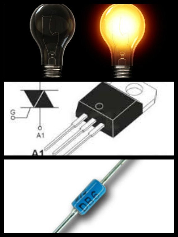
Engineering 101: Light Dimmer Using a Triac and Diac
Good day to you all, today i will discuss about a light dimmer using a triac and a diac. I hope you will learn something from it. There are many types of devices that will make a light dimmer but we use a triac and a diac to produce a light dimmer.
What is a Light Dimmer, TRIAC, and DIAC?
Light dimmer are devices that are used to lower or higher the brightness of the light. Using a potentiometer, that act as a rheostat, we can change the intensity of the light output.
TRIAC (TRIode for Alternating Current) is a device that is widely used in power control and switching applications. It is usually called a bidirectional triode thyristor or bilateral triode thyristor.
DIAC (Diode for Alternating Current) is a diode that only conducts a current after the breakover voltage that has been attain momentarily.
The procedures and the materials used
| Type of Material | quantity |
|---|---|
| Light Bulb (25 W) | 1 piece |
| Universal Printer Circuit Board | 1 piece |
| Socket | 1 piece |
| Switch | 1 piece |
| Potentiometer (500kΩ) | 1 piece |
| BT136 Triac | 1 piece |
| 1N5758 Diac | 1 piece |
| 0.12uF Capacitor | 1 piece |
| 3.3kΩ Resistor | 1 piece |
| wire | 2 meters |
This project involves the designing and planning of a light dimmer using a TRIAC and DIAC. There are two phases in designing a light dimmer using a TRIAC and DIAC. The first one is the simulation part and second one is the physical part where there is a designing on a universal printed circuit board (PCB).
We construct our circuit in simulation so that we can experiment if the design can produce a precise output or not. In simulation part, we do not need to buy components in testing the design we only need a simulation program running on a computer. In this case, we use multisim to simulate a light dimmer using a TRIAC and DIAC.
We ensure a slowly but surely process in making this project because we might end up buying a new materials if it fails.
After a couple of hours of making this project, this is our output of the circuit. It was indeed a simple light dimmer project. A simple can make it a better solution rather than a complex one.
We test it in a 220V AC source so that we will know it will work or not. Take note that this is the first time we test in a 220V AC source.

Conclusion
With our enormous brainstorming from the project, we learn how to design and construct the dimmer light circuit in physical part/hardware in universal PCB. This project helped us to know how to construct the circuit of dimmer that use in some houses using triac and diac and potentiometer as a rheostat. In the whole, we successfully design the light dimmer on the universal PCB and it worked.


You have been upvoted by the @sndbox-alpha! Our curation team is currently formed by @bitrocker2020, @zord189, @aaronleang, & @teachblogger . We are seeking posts of the highest quality and we deem your endeavour as one of them. If you want to get to know more, feel free to check our blog.