THE SCIENCE OF ROTOR MOTOR
ROTOR MOTOR
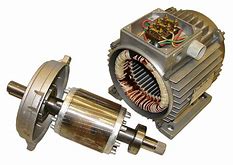
The rotor is a moving component of an electromagnetic system in the electric motor, electric generator, or alternator. Its rotation is due to the interaction between the windings and magnetic fields which produces a torque around the rotor's axis
 source
TYPES AND CONSTRUCTIONS OF ROTORS
Induction motors, generators and alternators sync have an electromagnetic system consisting of stator and rotor. There are two designs for the rotor in an induction motor: squirrel cage and wound. In generators and alternators, the rotor designs are salient pole or cylindrical.
SQUIRREL-CAGE ROTOR
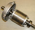
The squirrel-cage rotor consists of laminated steel in the core with evenly spaced bars of copper or aluminum placed axially around the periphery, permanently shorted at the ends by the end rings. This simple and rugged construction makes it the favourite for most applications. The assembly has a twist: the bars are slanted, or skewed, to reduce magnetic hum and slot harmonics and to reduce the tendency of locking. Housed in the stator, the rotor and stator teeth can lock when they are in equal number and the magnets position themselves equally apart, opposing rotation in both directions. Bearings at each end mount the rotor in its housing, with one end of the shaft protruding to allow the attachment of the load. In some motors, there is an extension at the non-driving end for speed sensors or other electronic controls. The generated torque forces motion through the rotor to the load.
 source
WOUND ROTOR
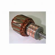
The wound rotor is a cylindrical core made of steel lamination with slots to hold the wires for its 3-phase windings which are evenly spaced at 120 electrical degrees apart and connected in a 'Y' configuration. It is a rotor with insulated windings brought out via slip rings and brushes. However, no power is applied to the slip rings. on the shaft of the rotor Brushes on the slip rings allow for external three-phase resistors to be connected in series to the rotor windings for providing speed control. Their sole purpose is to allow resistance to be placed in series with the rotor windings while starting. As the motor speeds up, the resistances can be reduced to zero.
 source
SALIENT POLE ROTOR
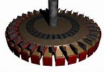
The salient rotor is a large magnet with poles constructed of steel lamination projecting out of the rotor’s core. The poles are supplied by direct current or magnetized by permanent magnets. The armature with a three-phase winding is attached to three slip rings with brushes riding on them and mounted on the shaft. The field winding is wound on the rotor which produces the magnetic field and the armature winding is on the stator where voltage is induced. Direct current (DC), from an external exciter or from a diode bridge mounted on the rotor shaft, produces a magnetic field and energizes the rotating field windings and alternating current energizes the armature windings simultaneously.
This rotor operates at a speed below 1500 rpm (revolutions per minute) and 40% of its rated torque without excitation
It has a large diameter and short axial length
Air gap is non uniform
Rotor has low mechanical strength
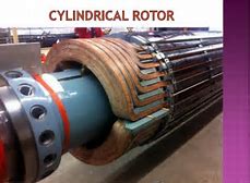
CYCLINDRICAL ROTOR
The cylindrical shaped rotor is made of a solid steel shaft with slots running along the outside length of the cylinder for holding the field windings of the rotor which are laminated copper bars inserted into the slots and is secured by wedges. The slots are insulated from the windings and are held at the end of the rotor by slip rings. An external direct current (DC) source is connected to the concentrically mounted slip rings with brushes running along the rings. The brushes make electrical contact with the rotating slip rings. DC current is also supplied through brushless excitation from a rectifier mounted on the machine shaft that converts alternating current to direct current.
The rotor operates at speed between 1500-3000 rpm
It has strong mechanical strength
Air gap is uniform
Its diameter is small and has a large axial length and requires a higher torque than salient pole rotor.
 source
OPERATING PRINCIPLE
In a three-phase induction machine, alternating current supplied to the stator windings energizes it to create a rotating magnetic flux. The flux generates a magnetic field in the air gap between the stator and the rotor and induces a voltage which produces current through the rotor bars. The rotor circuit is shorted and current flows in the rotor conductors. The action of the rotating flux and the current produces a force that generates a torque to start the motor.
An alternator rotor is made up of a wire coil enveloped around an iron core. The magnetic component of the rotor is made from steel lamination to aid stamping conductor slots to specific shapes and sizes. As currents travel through the wire coil a magnetic field is created around the core, which is referred to as field current. The field current strength controls the power level of the magnetic field. Direct current (DC) drives the field current in one direction, and is delivered to the wire coil by a set of brushes and slip rings. Like any magnet, the magnetic field produced has a north and a south pole. The normal clockwise direction of the motor that the rotor is powering can be manipulated by using the magnets and magnetic fields installed in the design of the rotor, allowing the motor to run in reverse or counterclockwise.
ROTOR EQUATIONS
Rotor bar voltage
The rotating magnetic field induces a voltage in the rotor bars as it passes over them. This equation applies to induced voltage in the rotor bars.

where:
 = induced voltage
 = magnetic field
 =conductor length
 =synchronous speed
 = conductor speed
TORQUE IN ROTOR
A torque is produced by the force produced through the interactions of the magnetic field and current as expressed by the given:


where:
 =force
 =torque
 =radius of rotor ring
 =rotor bar
INDUCTION MOTOR SLIP
A stator magnetic field rotates at synchronous speed

where:
 = frequency
 = number of poles
If  = rotor speed, the slip, S for an induction motor is expressed as

mechanical speed of rotor, in terms of slip and synchronous speed:


Relative speed of slip

FREQUENCY OF INDUCED VOLTAGES AND CURRENTS

Ref1 Ref2
Thanks for reading my post...
continue steeming...
Congratulations @veryboy! You received a personal award!
Click here to view your Board of Honor
Congratulations @veryboy! You received a personal award!
You can view your badges on your Steem Board and compare to others on the Steem Ranking
Vote for @Steemitboard as a witness to get one more award and increased upvotes!
The main thing is to understand how to maintain the durability and efficiency of the motor, for example through laminations from lamnow. The lamination process involves coating the steel sheets with an insulating film, which helps in protecting the motor from environmental factors like moisture, thus enhancing its durability.