World of fun and resistors. ¦ All things resistance and cracking a resistor's colour code.
Introduction.
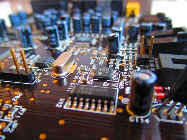
The resistor as a passive and mostly tiny component is known to be one of the most basic electronic devices around the world over. There's hardly any simple or complex electronic/ electrical system that doesn't require resistors or the application of it's theories for functional operation. That's because they’re simple and yet versatile. – From small battery operated toys in the toybox to the massive TV in your sitting room, resistors are everywhere.
Resistors and resistivity.
On a general scale, most materials could be seen as resistors. This is because they offer resistance to the flow of electric current through them, but in varying degrees. Some materials are simply doing better jobs at keeping current at bay.
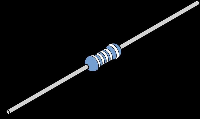
**A resistor is an electronic device that limits the free flow of charges (current) through a conductor. **
These guys are pretty boring components, – They do nothing to your device other than get warm and cold again. however, their use is paramount to the current and voltage distribution in a circuit.
One of the most common uses of a resistor is to limit the amount of current in part of a circuit. However, resistors can also be used to control the amount of voltage provided to part of a circuit and alsohelp create timing circuits.
The degree to which a particular material resists or limits the flow of current is termed as its resistivity. Another scientific term for this would be specific electrical resistance of that material. Resistivity is symbolized by the Greek letter ρ (pronounced as 'rho' ) and it's SI unit is the
ohm - metre (Ω⋅m).
Resistivity is pretty standard for every particular material, and relative in comparison to others. It is the resistance per unit length of a conductive material. (all things being equal.) Hence, a high resistivity value would imply that a material does not allow the passage of electric current through it freely enough, and a low resistivity indicates that a material more readily allows the flow of electric current.
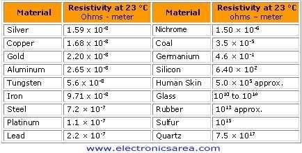
Here is a chart of the resistivity values of some common materials.
The SI unit of electrical resistivity is the
ohm - metre (Ω⋅m), and it is represented by the Greek letter ρ ( rho ).
Resistance of a resistor
The resistance of a resistor is the magnitude (numerical value) of resistance to current flow that a resistor gives. This shouldn't be confused with resistivity at all, – Which denotes the resistance of a unit of that material.
The resistance of a resistor depends on more than just the nature of the material. It is symbolized by the letter "R" and it's unit is the OHM (Ω). A bit about that in a while.
Some good examples of resistive materials are Mica, Glass, Rubber, Wood, plastic, air, etc.
As far as resistors go, their resistance isn't always the same for every size, shape and condition. This is due to a couple of factors.
Factors affecting the resistance of a resistor are:
• The length of the conductor wire: The longer the wire, the greater it's resistance value would be. hence a longer wire used for transmitting electrical energy would resist more current flow than a short one.
• The surface area of the conductor: The resistance of a conductor also directly correlates with the size of the conductor. A thicker wire would allow for a freer flow of electric current through it than a thin one –just like how a bigger pipe would allow the flow of more fluid through it.
• Temperature of the conductor: With increasing temperature, conductors tend to be more resistant to the flow of electricity through it.
• The resistivity of the conductor: Standard resistance value for a unit area of the conductor. It is constant for each material.
So for a material at a bound temperature, the mathematical expression would be
R ∝ (L/A)
Introducing the resistivity (effect due to the nature of the material) as the constant of proportion denoted p (rho) forms an equation:
R=(ρL)/A
Where,
L = length in meters
A = cross sectional area in sq.meter (m^2)
ρ = resistivity in ohm–meters
R = Resistance in ohms
"Sherlock Ohms!"

*Georg Ohm did his work on resistance in the years 1825 and 1826, and published his results in 1827 as the book *Die galvanische Kette, mathematisch bearbeitet ("The galvanic circuit investigated mathematically")
What exactly is the "ohm"?
Resistance in a material is caused when the flowing charges collide with the atoms in a conductor. Due to this constant collision, energy is given off in the form of heat, and we see the conductor getting warm a bit.
The ohm is the measurement quantity of resistance, which produces one joule of energy (in the form of heat) in one second, when one ampere of current is flowing through it.
Makes sense, yeah?
So how do we relate this to the resistance of the circuit? What is the relationship between the current flowing through a conductor, the voltage across the conductor and the resistance of the conductor?
If there is a potential difference of 1 volt between two ends of a conductor and the flowing current through it is 1 Ampere, then the resistance of that conductor would be 1 Ohm (Ω).
Mathematically;
1Ω = 1V/1A
Stating Ohm's law.
According to Wikipedia:
Ohm's law states that the current through a conductor between two points is directly proportional to the voltage across the two points.
I ∝ V
Mathematically introducing a constant (the resistance), The formula becomes:
I = V/R.
A simple way to remember these equations would be to use the ohm triangle, which is really self explanatory.
Ohms law also applies in alternating-current (AC), circuits as long as the resistor does not contain inductance or capacitance.
Let's take a quick quiz here, be sure to attempt the question before looking at the answer to check.
Quick quiz 1: What current passing through a 10kΩ resistor will produce a voltage of 8V across it?
(see answer below)
Using ohm's law (V = I × R), we have that;
I = V/R
V = 8V
R = 10kΩ which is equal to 10 × 10^³, = 10000Ω
Hence, calculating would give us;
8/10000
I = 0.0008A
See? a no brainer! 😀
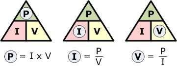
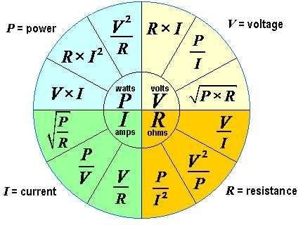
Here is a chart of the various other formulas used in calculating the resistance, energy and power, in an ohmic circuit.
Materials for making a resistor.
The choice of material for making a resistor is often a trade-off between costs, precision and other requirements, and tailored with a particular use in view. The carbon-composition resistor is the most common one. It is produced by mixing fine grains of carbon (graphite) with clay, and then hardening it.
Below are some other techniques and materials used.
• Wirewound: Basically, resistors could be constructed by winding a special metal alloy wire, such as nichrome, around a non-conductive core. They are durable, accurate, can handle higher currents than a carbon-composition resistor of the same physical size.
• Metal films and Carbon films: Metal films are the most commonly used material in modern times because they are less influenced by temperature variations.
• Metal foil resistors: Metal foils can be used to fabricate a resistor too. They are constructed by cementing a special alloy cold rolled film onto a ceramic substrate.
Types of resistors.
There are two basic types of resistors. namely;
1. Linear resistors
2. Non-linear resistors.
Resistors in which the current value is directly proportional to the applied voltage are termed as linear resistors.
Linear resistors are of two types;
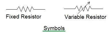
Fixed resistors – resistors whose value is fixed and cannot he changed.
Variable resistors. – Resistors whose resistance values are not fixed. The resistance value of variable resistors can be altered through dials knobs, and screws, etc... examples of some common variable resistors are:
• Potentiometers
• Rheostats

Quick Quiz 2: What's difference between a potentiometer and a Rheostat? See answer below question
You guessed right! A Potentiometer and a Rheostat are the same, the only difference here is that a potentiometer alters the voltage (PD) of the circuit while the rheostat is used for altering the current. either way, both have effect on the resistance too.
High five!

Resistor colour coding.
With increased production of resistors, engineers and scientists saw the need for standardized resistance values. These standards simply would be ways to measure and easily classify these resistors and their properties.
Resistor colour coding is one of the most common ways of standardizing resistors, it dates back to the 1920's when printing technology wasn't developed yet. –So it was hard to make readable prints on tiny materials.
The resistance value and tolerance are indicated by several colored bands around the body of the resistor. These colours are pegged to some particular values on a standard resistor colour code chart.
The colours used are:
Black, Brown, Red, Orange, Yellow, Green, Blue, Violet, Grey, White, Gold, Silver
How to read a colour coded resistor.
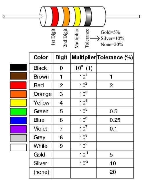
Nowadays, the color code is used mostly on axial resistors up to one watt. There can be as much as three to six colour bands on body of the resistor. however, we will be dealing with the 4 coloured band because it is the most common one.
• The first 2 bands make up the significant digits. The values are written with respect to the colours on the chart:
For black, write 0
For brown, write 1
For red, write 2
For orange, write 3
And so on...
• The third band represents the multiplier. This multiplier will shifts your decimal place. It is used to multiply the previous two values.
If the colour is brown, multiply by 10¹
If black, multiply by 10²
And so on...
• The fourth color band signifies tolerance.
If the colour is gold, it is 5%,
If silver, it is 10%
If the resistor doesn't have a fourth band, the default tolerance is ±20%.
Quick quiz 3: Find the colours for the resistor 560 ohm, 5%. Refer to the table above.
From the table above,
5 is green.
6 is blue
0 is black, but since this is the third band, we write down it's multiplier value instead. (10¹ = 10)
5% is gold.
So we have 56 ×10 = 560 ohms 5%
Our colours are: Green Blue Black and Gold
Feel free to play around with the colours to get resistors of different resistance values.
Combining resistors. – Series and parallel connections.
In most electronic/electrical circuits, resistors with standard values are combined to reach a required value suitable for a particular purpose. This is like joining smaller resistors to make an even bigger resistors. It is done by connecting it in two ways:
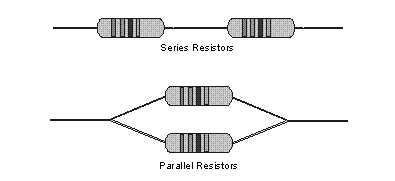
• In series with each other.
• In parallel to each other.
In series.
For series connection, successive resistors are connected from end to end. Hence, the current passing through each resistor is the same, and the total resistance (commonly called equivalent resistance) would be the sum of the resistance values of the resistors used.
Supposing, three resistors with values 3 ohms, 4 ohms and 5 ohms are connected to each other in series, and a potential difference (PD) of 12v is used, what do we make of this?
Since they are connected in series, it simply implies that the same value of current flows through each of the resistors, and the equivalent resistance value can be calculated by summing up the individual resistance values of the resistors.
R = r1 + r2 + r3
3 + 4 + 5 = 12Ω
Having known the equivalent resistance, the current through the circuit can be calculated.
I = V/R. = 12/12 = 1A (ampere)
In parallel.
For parallel connection, the voltage through each resistor is the same, and the inverse of the equivalent resistance is equal to the sum of the inverse values for all parallel resistors. a bit much grammar to chew on. It is best understood mathematically:
1/R = 1/r1 + 1/r2 + 1/r3
Supposing, three resistors with values 3 ohms, 4 ohms and 5 ohms are connected to each other in parallel, and a potential difference (PD) of 12v is used, what do we make of this?**
This indicates that the same voltage would course through each of the resistors. the equivalent resistance of this circuit is calculated thus;
1/R = 1/r1 + 1/r2 + 1/r3
1/R = 1/3 + 1/4 + 1/5
1/R = 47/60 (by L.C.M)
Cross-multiplying these values;
R = 60/47 which gives
R = 1.3Ω ohms. approx.
Right, done!
Applications of resistors.
As the most basic component of an electronic circuit, there is a huge variation in fields of applications for resistors. Many electrical devices are based on electrical resistance and Ohm's law, even if they do not have little components in them that look like the usual resistor. from precision components in digital electronics to measurement devices for physical quantities. some common use of the resistor are:
• In heaters and lightbulbs.
By resisting current, resistors convert electrical energy into heat. and as such, they make really good heating elements for heaters, electric stoves and similar devices. Light bulbs work because the very high temperature caused as a result of the resistance turns the metal filament white-hot, thus, producing light.
The formula, P = I^2 * R, where P is heating power in watts, I is current in amps, and R is resistance in ohms, determines the amount of heat given off by a resistor.
In the voltmeter.
A voltmeter is simply an ammeter with high value resistors inside of it to help minimize current, thus allowing for the voltage to be read more accurately.
• In fuses.
A fuse is a length of metallic wire with low melting point. Basically, it limits the flow of current through it by its resistive value. If the current flowing through the fuse becomes dangerously high, the temperature of the fuse rises and the fuse melts, thus saving the entire components in the circuit.
• Also, because resistors limit electric current through a material, it is mostly used to provide a specific voltage for an active device such as a transistor.
• Resistors are also very useful in sensors, polygraph, voltage division, in cell phone and TVs, etc.
Thank you for reading, hope to have imparted knowledge of some magnitude. feedback is highly coveted by this blogger! Feel free to point out disagreeable facts in the comment section below.
Until next time.


References consulted
This is deep! Welldone Engineer
Thank you jeline...
Great post...! Are you Engineer ? I'm also an Electrical Engineer. Thanks for share the useful post....
Upvoted...!
Yes I am an engineering student in college.
Glad it was useful to you.
Mr @pangoli physics lecturer
Welldone sir
Hahaha.. Thanks dear, @ponmile
Nicely done mate, I see you have put a lot of work into this and it is appreciated.
Thank you Sir... 😃
Looks pretty solid to me. This is the basics of electricity. All other things is sort of somewhat based on this. Well researched.
Thanks bro.. I appreciate this. 😃
You rock.
Wow! This means a lot to me, coming from you
Nice one brother
Thank you bro
Nice one boss
Great post... @alot of physics, almost like a textbook to me
Yeah bro, pretty basic stuff here. Thanks for stopping by
Looks like I am reading text book of my school. :)
Sir Hafiz! Glad you liked it! I tried to be as detailed as possible without much technological jargons.
You got a 0.81% upvote from @upme requested by: @pangoli.
Send at least 1.5 SBD to @upme with a post link in the memo field to receive upvote next round.
To support our activity, please vote for my master @suggeelson, as a STEEM Witness
This post has received a 0.20 % upvote from @drotto thanks to: @banjo.
Wow, certainally a lot of information contained in this post my friend. I learned a lot about resistors. I once had a transistor radio and took it apart, it was fascinating!🐓
Excellent! Lol... Hope you felt the thrill of pulling things apart...🤓 It's a world of fun afterall... Fun and resistors 😎