Bob Higgins to try electro-magnetic stimulation in his next reactor
Bob Higgins is conducting a series of experiments into the New Fire in the spirit of Live Open Science. He has built a insulated reactor and is to test the effect of a magnetic field in his next experiment.
Bob says:
The field coil is done (see Figure 1). This will be used for electromagnetic excitation of the reactor by having this suspended around the insulated reactor tube k-26 bricks. The coil is 4 layers of 15 gauge heavily enameled copper wire with a total of 130 turns epoxied together while winding. The length is 2.25" (57mm) and the inside square dimension is 3.5" (89mm) with rounded corners:
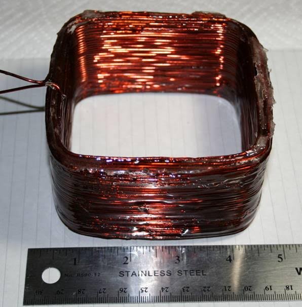
The inductance is expected to be about 1.2mH (calculated) and should produce a magnetic field of about 28 gauss on axis per ampere of current. I plan to add a series 1uF capacitor and drive it at resonance with a high power audio power amplifier. I should be able to get at least 5A peaks for 140 gauss peaks at the expected 4600 Hz resonance.
The script driven Labview control program is being modified to accept a new script command, "W", which will play a specified .wav file from the computer to drive the audio PA and the coil. Initially this .wav file will only be a 5-10 second pulse of a 4600 Hz sine wave, but there is nothing keeping me from having the .wav file be a chirp, or any other waveform. The coil will be series resonated for sine drive at resonance to provide a greater current and magnetic field. If I drive the coil directly, the reactance of the coil will limit the current and broadband magnetic field magnitude, but then almost any waveform can be used.
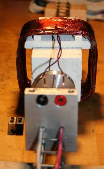
Here are a couple of pictures of the reactor assembly with the added coil. Tomorrow I am going to measure the resonant frequency on the bench. The block on the top of the aluminum plate with the banana jacks is removable because I must remove the coil to access the reactor tube and heater inside the K-26 insulating blocks.

I have measured the coil around the reactor. The result is that the inductance is somewhat higher than calculated (1.94 mH), the capacitance is somewhat smaller than labeled (0.82 uF). The resulting resonance frequency is 3.99 kHz and the effective series resistance at resonance is 3.05 ohms. The Q is relatively low which means that resonance drift with temperature shouldn't be much of a problem.
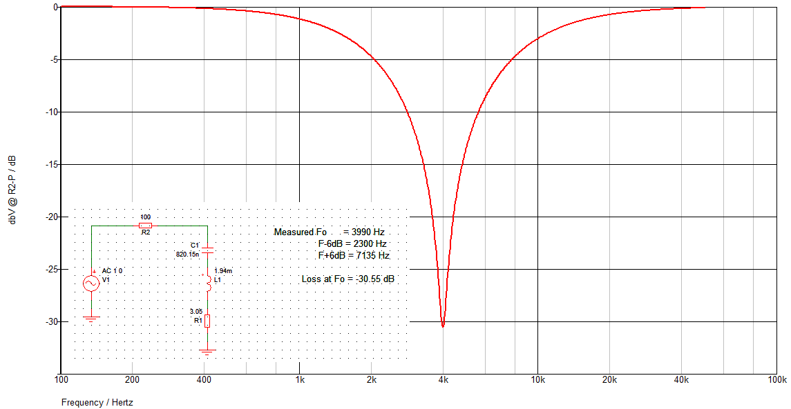
In this simulation L1 is the big square coil. R1 is the DC resistance of the coil. C1 is the non-polar capacitor that I will add in series. R2 is only put there for measurement. Measure the voltage amplitude from the top of C1 to ground while you sweep the frequency of the audio signal generator. What you will see is a big dip in voltage as C1-L1 go into series resonance. At series resonance the reactance of C1 cancels that of L1 and you are only left with resistance, R1 at that resonant frequency. It becomes an ~100:1 resistive divider at the resonant frequency. Once you have found the resonant frequency, just create a .wav file with that frequency as a tone.
The C1-L1 WILL resonate at some frequency, approximately 1/(2pi sqrt(L1 C1)). The trouble is that you only know L1 and C1 approximately and need to find the exact resonant frequency to use in making the driving .wav file. Making the .wav file with a tone at the measured resonant frequency is trivial with an audio editor.