Tesla's Magnifying Transmitter - Part 2: High Voltage Generation
The road to extremely high voltages knows many traps and pitfalls. First of course, in its containment and safety, but that is not today’s topic. Today I want to talk about how to generate voltages of well over 1 million volt.
Starting with an ordinary transformer which is just two coils (a primary and a secondary) on an iron core, this iron core is the first thing that gets in our way, for two reasons:
- the obvious risk of creating shorts
- the more power you need, the more iron you need to transfer that power
Luckily, by raising the frequency of the (alternating) current (the grid provides 50 or 60 Hz depending on where you live, but this can be raised to almost 1,000,000 Hz before you run into new problems) you need less iron and from a certain frequency upward you do not need any iron at all.
The next problem is the voltage between adjacent turns. By organizing the turns into 1 layer and choosing the frequency such that it matches the natural resonance frequency of the coil, this problem is minimized and thus we arrive at the well known Tesla coil.
With such a coil voltages of up to 400,000 are easily obtained, and when you put in more power you can get even higher voltages.

Changing the frequency
In Tesla’s days there were two ways to create high frequency AC. First of course you can speed up your generator and let it have more poles. That way you can go up to a few 10,000’s alternations per second. Usually that is not enough and this is where the spark gap oscillator comes in.
The combination of a coil and a capacitor forms a resonating circuit (like a tuning fork) and the spark gap is like a hammer. The spark gap hits the resonating circuit, as it were, and this produces a high frequency tone. Instead of a very brief spark, you can also prolong the spark a little, in which case the circuit more resembles a pan flute; the spark now being like an air stream blown over a resonating circuit.
You may start out with rectified AC or DC or you can use a slow AC (like we have from our mains), you can use single phase or 3-phase AC, they all have some points of attention, but they can all be used.
Today we have power transistors through which we have very precise control over currents. This offers new ways to create the high frequency currents that are needed.
Finally we now have very powerful RF amplifiers that we can use to amplify a signal from a signal generator and in that way we have the ultimate control over the high frequency current that we use in our Tesla coil.
The transformer dilemma
The problem that you are now facing is that the energy that is put into the primary coil, gets transferred to the secondary -just as intended- but from there gets transferred back to the primary again -which you don’t want. So the energy moves back and forth between these two coils.
This creates a dilemma, you want a closely coupled coil to transfer energy into the secondary, yet you want a loosely coupled coil so the secondary can resonate freely.
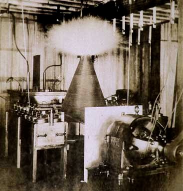
Tesla’s first step towards solving this was changing the geometry of the coil from cylindrical to conical. Thus the bottom can be closely coupled to the primary while the rest of the coil is more free.
- up to this point you can read this story in Tesla’s own words in his article of 1899 March 29th, “Some Experiments in Tesla’s Laboratory with Currents of High Potential and High Frequency” published in the Electrical Review.
Intermezzo on wavelengths and velocity factor
Imagine a coil with two open ends, then imagine electrical charge bouncing back and forth between both ends of the coil. Let’s say the charge first moves to the right end, gets compressed until it stops moving, and then it starts moving to the left and gets compressed on that end, etc. What you now see is that the ends of the coil function as temporary storage -which is the same function as a capacitor has- while the middle of the coil acts as an inductor -an actual coil. Near the ends of the coil there is little movement of charge, in the middle there is a lot. In the ends of the coil you will see a potential rise, while the middle remains neutral. Electric charges do not travel all the way from the left to the right end and therefore it appears as if the signal bounces between both ends at a velocity greater than the speed of light. This apparent velocity relative to the speed of light we call the velocity factor.
So, for example, in a coil with a velocity factor of 2 it looks as if a signal travels between both ends at twice the speed of light, but the average charge moves only half the length of the coil. In actual reality it isn’t the coil’s charge but the charge density that moves half the coil’s length, but I want to keep this as simple and intuitive as possible.
This charge movement resembles theoretical gas movement in a flute with both ends closed. In this movement we have a node at both ends and an anti-node in the middle. Thus the distance between both ends equals half the wavelength belonging to the frequency.
Back to our coil we have two current nodes at the end of the coil and an anti-node in the middle. While looking at the voltage, we see one node in the middle and two anti-nodes at both ends.
This situation we call half wavelength resonance.
If we now connect one end of the coil to the ground, as is common in Tesla coils, charges do no longer get compressed on this end. Instead they flow freely into the ground, leaving the voltage at zero at all times. The nature of resonance now changes as we now have one current node at the top of the coil and one current anti-node at the bottom, making the distance between both ends one quarter wavelength. Looking at voltages, we see one voltage node at the bottom of the coil and one voltage anti-node at the top. We can compare this with a flute that has one end open and one end closed.
A Tesla coil is usually operated in quarter wavelength resonance, as in this way one end has a constant low voltage which makes it easy to put a primary coil on that end, while at the other end we get our high voltage.
Other modes of resonance are possible (three quarter, five quarter etc.) but for the sake of simplicity I’ll just leave it here.
Final solution to the transformer dilemma
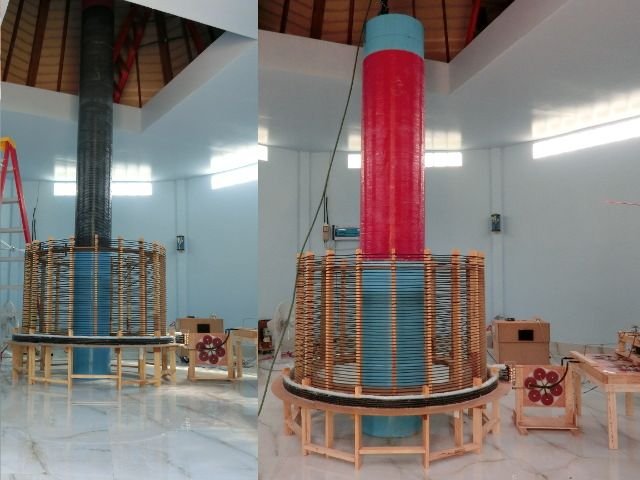
The final solution is to split the secondary coil into two coils, one tightly coupled secondary and a magnetically free, so called “extra coil”.
In the secondary you want to have a one quarter wavelength resonance and in the extra coil a half wavelength resonance, so that in the combined coil you’ll have three quarter wavelengths.
This solution gives us another benefit as well. Having two coils, a primary and a secondary, the output voltage depends on the ratio of their inductances. You would therefore want to make a primary with as few turns as possible, i.e. 1 turn. Having so little inductance in the primary requires to use relatively large primary capacitors which are often the most expensive part of a Tesla coil.
Having three coils, the resonant action in the extra coil determines the output voltage, which gives you the freedom to have more primary inductance and a cheaper capacitor.
Enter the velocity factor
This part is not described by Tesla but is what I learned from my experiments.
If a wave travels from a medium where it travels fast into a medium where it travels slower part of the wave energy gets reflected as you intuitively would expect. What is less intuitive is that the other way round you also get a partial reflection. Only when the velocities are equal there is no reflection. In the design of my coils I have chosen a velocity factor of 1 for both coils, thus we get a (near) perfect energy transfer between the secondary and the extra coil.
Intuitively I would say that if the extra coil has a higher velocity factor the energy transfer from secondary to the extra coil would be easy, while in the other direction it would be much harder. Thus we could ‘trap’ the energy in the extra coil and would expect better results.
Unfortunately that did not work out as expected but it remains a topic for further investigation.
If you are interested in reading more on this part of my research, you can download this report (about 3MB).
As always: If you have any questions, or want me to elaborate on some point, please do not hesitate to ask.


Hello again, @mage00000,
Thank you very much for your intuitive description of how these coils work and of the things you have learned. Thank you also for sharing your more detailed research papers.
I have a small tesla coil, once built for me by a friend. I take it out to admire it and to "show it off" once in a while. Reading your articles here on Steemit will help me to begin better understanding how it works. I appreciate you! 😄😇😄
