Acetone Production Process From Iso-Propyl Alcohol
After the isopropyl alcohol evaporates goes to reactor and acetone is formed as a result of catalytic dehydration. The gas stream leaving the reactor (acetone, water, hydrogen, isopropyl alcohol) is sent to the condenser. Most of the acetone in the stream is condensed with water and isopropyl alcohol. The condensate leaving gas stream contains a small amount of acetone and isopropyl alcohol. This stream is washed with water in an absorption column and acetone and alcohol are absorbed. The stream from under the washer (absorption column) and the liquid stream from the condenser (condensate) are combined and sent to the distillation column to obtain pure acetone. Pure acetone is removed from the top of the distillation column. Under this column, a stream containing water and isopropyl alcohol is taken and sent to a second distillation column. The upper stream of the distillation column No. 2 is a mixture of azeotrope water-alcohol that contain 91% alcohol. This stream is transferred to the reactor.

ZnO-Cu catalyst is used in the reactor, the reaction is carried out at a temperature of 400-500 °C and a pressure of 4.5 bar. The acetone yield in the process is 98%. Each conversion rate of isopropyl alcohol from the reactor is about 85-90%.
- The process flow diagram is drawn
- The information flow diagram is drawn
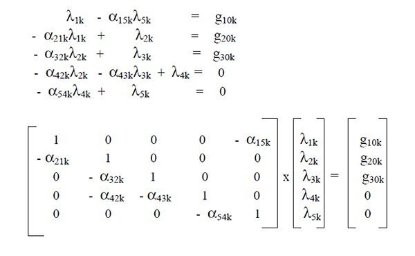
- The mass balance for the components is established and written in matrix form
- Separate fractional coefficients are determined for the current components of the process and the mass balance of the matrix form is rewritten for each component

The flow diagram of the process is drawn with block diagrams and information flow diagram can be seen in the figure. The symbols used to establish the mass balances for this process are given below.


If the equations are arranged and written in matrix form,
Determination of Fraction Coefficients
Components (k = 1-5); k = 1 isopropyl alcohol, k = 4 acetone, k = 3 hydrogen, k = 4 water
Process units (i,J); 1 = reactor, 2 = condenser, 3 = washer, 4 = first distillation column, 5 = second distillation column
The designer should specify certain process and equipment specifications for the project run before designating the fraction coefficients. These values also called design variables are the values that the designer can change over and over again in order to achieve the desired results.
For example, in the process of acetone production from isopropyl alcohol, the following values are considered as initial values for design variables.
- Isopropyl alcohol conversion rate at each pass through the reactor is 90%
- 90% of isopropyl alcohol is condensing in the condenser
- 99% of the isopropyl alcohol in the washer is absorbed and it is passed to liquid phase
- The impurity ratio in the produced acetone is allowed to contain maximum of 1% of isopropyl alcohol
- Concentration of at least 80% of the acetone in the flow entering the condenser is desired
- 99% of the acetone in the washer should be absorbed
- 95% of the water is condensed in the condenser
- Maximum 1% of the water entering the washer is pushed into the gas phase
In addition to these determinations, acetone, water and hydrogen present in the reactant stream are known to be from the reactor leaving the reactor without entering the reactor. Hydrogen is not condensing in the condenser, is not absorbed in the washer and so it is in continuous gas phase. The stream leaving the second distillation column and re-reacting is a 91% alcohol-water azeotrope mixture.
Basically in calculations,
- Input = 100 kmol / hr of isopropyl alcohol, g101 = 100
- Since the yield of acetone in the reactor is 98%, g202 = 98
- Also the yield of hydrogen in the reactor is 98%, g203 = 98
The fraction coefficients and the numerical values of the externally supplied currents are given collectively in the following chart.

P.s. The amount of water sent from the outside to the absorption column depends on the column design. For that reason, the amount of water sent to the colum (kmol / hr) = g304
References:
- Peters, M.S., Timmerhaus, K.D., West, R.E., “Plant Design and Economics for Chemical Engineers,” 5th ed., McGraw-Hill, New York (2003)
- Sinnot, R.K., “Chemical Engineering Design”Elsevier, 5th edition, Pergamon Pres, 2005
- Perry, R.H., Green, D.W., “Perry’s Chemical Engineers’ Handbook,”7th ed., Mc-Graw Hill, New York (1998)
- Uldrich, G.D., A Guide to Chemical Engineering Process Design and Economics, John Wiley and Sons New York 1984, 473 p
As a follower of @followforupvotes this post has been randomly selected and upvoted! Enjoy your upvote and have a great day!
Congratulations! This post has been upvoted from the communal account, @minnowsupport, by Yaser from the Minnow Support Project. It's a witness project run by aggroed, ausbitbank, teamsteem, theprophet0, someguy123, neoxian, followbtcnews/crimsonclad, and netuoso. The goal is to help Steemit grow by supporting Minnows and creating a social network. Please find us in the Peace, Abundance, and Liberty Network (PALnet) Discord Channel. It's a completely public and open space to all members of the Steemit community who voluntarily choose to be there.