HOMEMADE CYCLING POWERMETER
Step 1: The principle
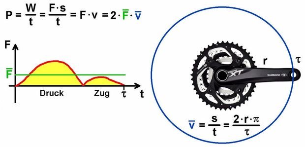


To calculate the power, we have to determine the current force, which is spent by the foot on the pedal. For this purpose I clued four strain gauges (http://www.ebay.com/itm/5Pcs-Pressure-Sensor-Precision-BF350-3AA-BF350-350-Strain-Gauge-Resistance-/361278029289?hash=item541dd93de9:g:oOYAAOSwstxVOFv2) on the sides of my old crank. To get a Signal depending on the load I arranged them in a so called Wheatstone-Bridge.
During one full rotation I sum as many forces as possible and calculate the average. Combined with the average velocity (2 * Pi * crank-radius / rotation-time) I get the power P.
To know the proportionality between the force F and the output-voltage U I strained the crank with different masses and myself (a lot of mass ;-)). The rise of the line is in my case 292 Newton/Volt.
For the amplifier I took a LF353 with a gain of 330. With this Setup I get Output-voltages between 1 and 4 V. I decided to start at 1V to avoid a negative drift and late response. Therefore I have to determine the offset at the beginning of the measurement and subtract this offset from the following voltages.
Step 2: The setup


For the power-supply I use two lipo-battery packs (7.4V, 1200 mAh for the receiver and a smaller 600 mAh one for the transmitter).
To save space I use an arduino nano and the NRF24L01 are responsible for the communication. They work great and you can send as many values as you want. In my case I send the power (P) and the rounds per minute (rpm).
I also had to check, when a full rotation has accured. To avoid a sensor, which has to be mounted on the bike-frame, I decided to use the gyroscope MPU-6050. The accuracy is about +-3 degree per full rotation, which is satisfying.
Step 3: The completed crank and receiver
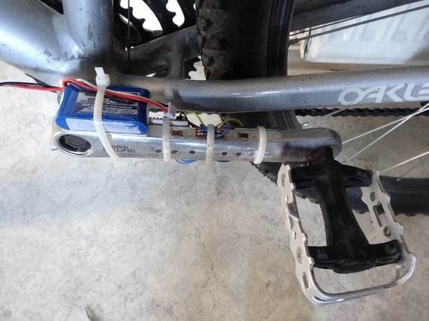

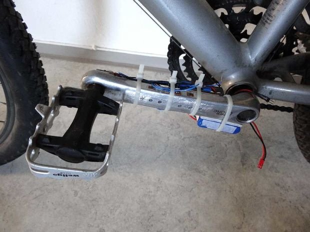


The challenge was to fix up all the components (power-supply, gyroscope, NRF24L01, amplifier, arduino) on one crankarm but I succeded. I fixed them with double-sided tape and cable ties.
To mount the receiver on the bar I use the clamp from a bicycle-lamb.
Step 4: The results


After calibration and programming I first tried my powermeter indoor on my training roller. I got reasonable values and therefore I went outside. Heureka, it works :-)
Finally I can say, that it's possible to build a simple and working powermeter for
2 x arduino nano ..... 10 USD
2 x NRF24L01 ......... 5 USD
16x2 LCD ................ 5 USD
4 x strain gauges ..... 10 USD
2 x Lipo battery pack ..... 15 USD
MPU-6050 ..................... 3 USD
electronic parts .............. 7 USD
less than 55 USD.
Here is the video:
To be continued... @itstudent
I am sorry for my no perfect English! I will try to write correctly!
If you liked this post write a comment indicating my nickname @itstudent, I will be very grateful! Thank you for attention! Do not forget to subscribe and put your up Vote!
This post has received a sweet gift of Dank Amps in the flavor of 1.92 % upvote from @lovejuice thanks to: @ideagenerator. Vote for Aggroed!