Want to Make PLC Programming Your Field of Expertise? : Gain the Basic Knowledge
The Knowledge to PLC System

"The PLC system is the major key in the technology and industrial sector today. PLC or Programmable Logic Controller is the system that makes machinery and systems work automatically... It’s a quite complicated process to make all machinery become automatic. This system is responsible for all the growth in the industry, manufacturing process, and even entertainment. Without such system, Transportation, manufacturing to amusement rides or movie making process can’t be done. That’s why PLC system is very important and needed for all kinds of industry."
Pedro Barretto
Aside from having the knowledge of understanding PLC internal hardware and programming, view the online status of the program, make modifications to the program, download/upload programs for backup and perform new control tasks, being able to know the usage of the software to perform basic access to the PLC memory is essential to be called a "programmer".
The Programming Language
Setting the Programming Language for the Editor
Before you generate a particular block or a source file, select the programming language and editor via the object properties. This selection determines which editor is started when the block or source file is opened.
Starting the Editor
Start the appropriate language editor either in SIMATIC Manager with a double-click on the corresponding object (block, source file, etc.), by selecting the menu command Edit > Open Object or click on the corresponding toolbar button.
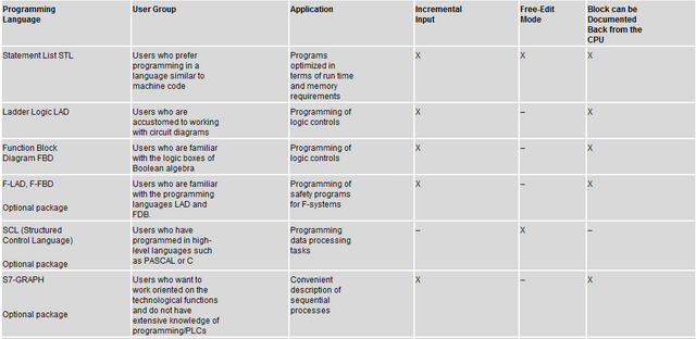
To create an S7 program, the programming languages listed in the table are available to you. The STEP 7 programming languages LAD, FBD, and STL are supplied with the standard STEP 7 software package. You can purchase other programming languages as optional software packages.
You then have the choice of a number of different programming philosophies (Ladder Logic, Function Block Diagram, Statement List, standard language, sequential control, or status graph) and whether to use a text-based or a graphic programming language.
Select a programming language to determine the input mode (X).

If blocks contain no errors, you can switch between Ladder Logic, Function Block Diagram, or Statement List format. Program parts that cannot be displayed in the target language are shown in Statement List format.
Under STL, you can generate blocks from source files and vice versa.
The System Memory Areas
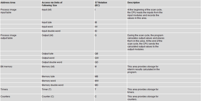
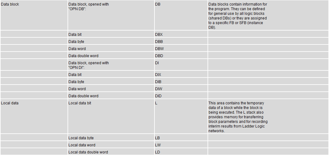
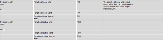
Every Programmable Logic Controllers (PLCs) have a memory map. The memory is divided into three portions: the program, word, and discrete registers. The program which is on a ladder logic and word registers are typically stored in FLASH memory, whereas the discrete register is stored in RAM memory.
SetReset Timer
Syntax: SRT (A1, A2, T)
The SRT instruction (Set/Reset Timer) is an on delay unit, operated with one set and one reset input. The set/reset inputs are pulse-driven. This means that the event is triggered by a positive edge (pulse) and not by TRUE or FALSE. The SRT instruction forms the expression A0, depending on the expressions A1 (set input), A2 (reset input), and the time T according to the following syntax:
A positive edge (change from FALSE to TRUE) at A1 (set input) starts the time T, regardless of whether the timer is running. A0 is set to FALSE.
A positive edge (change from FALSE to TRUE) at A2 (reset input) stops the time T, regardless of whether the timer is running. A0 is set to FALSE.
A0 = TRUE if the time T has expired.
A0 is initialized with FALSE on program start.
If a simultaneous positive edge occurs at A1 (set input) and at A2 (reset input), A1 is ignored.
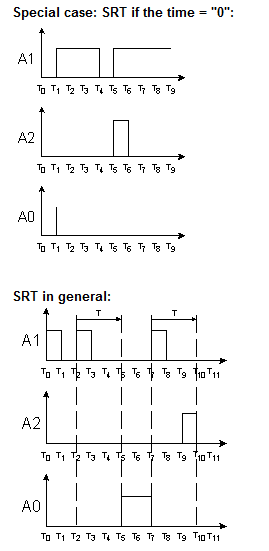
The SRT instruction monitors the status between two expressions. A positive transition at expression 1 triggers the delay time. A positive transition at expression 2 stops the delay time. If the delay time expires before it is stopped by a transition at expression 2, the logical status of the resultant expression is set to "1". The resultant expression maintains the same value until the next positive transition at expression 1 or expression 2. If the logical level of both expressions changes within the same cycle, the result is FALSE since expression 2 is of higher priority.
Examples:
SRT(I1.0, I1.1, 1000)

SRT( "Trigger1", "Trigger2", 2000)
Note
The expressions A1 and A2 should not contain any of the following qualifiers:
ONDT

EN

EP

SRT
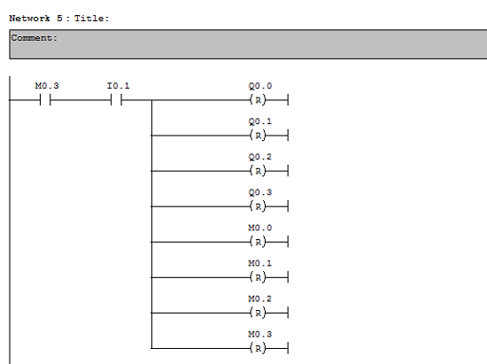
The Assignment List
The Assignment lists show you which addresses are already assigned in the user program. This display is an important basis for troubleshooting or making changes in the user program.
The I/Q/M assignment list display gives you an overview of which bit in which byte of the memory areas input (I), output (Q), bit memory (M), times (T) and counter (Z) is used. The I/Q/M assignment list is displayed in a working window.
The working window's title bar shows the name of the S7 user program to which the assignment list belongs.
I/Q/M Table
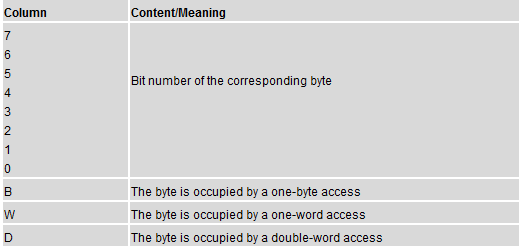
Each line contains one byte of the memory area in which the eight bits are coded according to their access. It also indicates whether the access is of a byte, word, or double word.
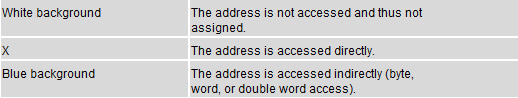
Identification in the I/Q/M Table
Columns in the I/Q/M Table
Example
The following example shows the typical layout of an assignment list for inputs, outputs, and bit memory (I/Q/M).
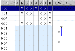
The first row shows the assignment of input byte IB 0. Inputs for address IB 0 are accessed directly (bit access). The columns "0", "1", "2", "3", "5", and "6" are identified with "X" for bit access.
There is also word access to memory bytes 1 and 2, 2 and 3 or 4 and 5. For this reason, a "bar" is shown in the "W" column, and the cells also have a light blue background. The black tip of the bar shows the start of word access.
T/C Table
Each row displays 10 timers or counters.
Example
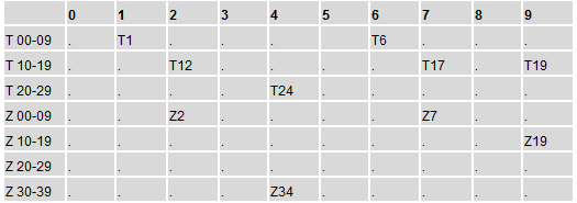
In this example, the timers T1, T6, T12, T17, T19, T24 and the counters Z2, Z7, Z19, Z34 are occupied.
Safety Measures When Forcing Variables

Beware of Injury to Personnel and Damage to Property
Note that when using the "Force" function, any incorrect action could:
Endanger the life or health of personnel or
Cause damage to machines or the whole plant.

Caution
Before you start the Force function you should check that nobody is executing this function on the same CPU at the same time.

A Force job can only be deleted or terminated with the menu command Variable > Stop Forcing. Closing the force values window or exiting the "Monitoring and Modifying Variables" application does not delete the forced job.

Forcing cannot be undone (for example, with Edit > Undo).

Read the information on the Differences between Forcing and Modifying Variables.

If a CPU does not support the Force function, all menu commands in the Variable menu linked with forcing are deactivated.
If the output disable is deactivated with the menu command Variable > Enable Peripheral Output, all forced output modules output their force value.
Establishing the Safety Requirements
Decide which additional elements are needed to ensure the safety of the process - based on legal requirements and corporate health and safety policy. In your description, you should also include any influences that the safety elements have in your process areas.
Defining Safety Requirements
Find out which devices require hardwired circuits to meet safety requirements. By definition, these safety circuits operate independently of the programmable controller (although the safety circuit generally provides an I/O interface to allow coordination with the user program). Normally, you configure a matrix to connect every actuator with its own emergency off range. This matrix is the basis for the circuit diagrams of the safety circuits.
To design safety mechanisms, proceed as follows:
•  Determine the logical and mechanical/electrical interlocks between the individual automation tasks.

•  Design circuits to allow the devices belonging to the process to be operated manually in an emergency.

•  Establish any further safety requirements for safe operation of the process.
Creating a Safety Circuit
The sample industrial blending process uses the following logic for its safety circuit:
• One emergency off switch shuts down the following devices independent of the programmable controller (PLC):
Feed pump for ingredient A
Feed pump for ingredient B
Agitator motor
Valves
• The emergency off switch is located at the operator station.
• An input to the controller indicates the state of the emergency off switch.
Below would be my second operational sequence to share. Hoping this could be a great help especially for Mechatronics students like me that could find this.
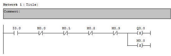
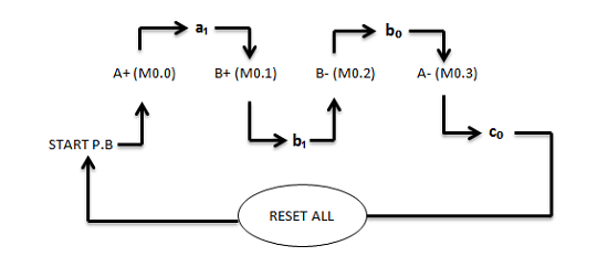
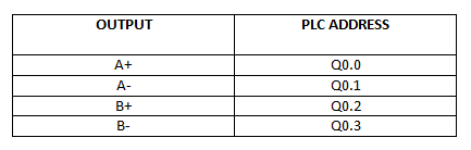
Operational Sequence : A+ B+ B- A-
With condition that pressing again the Start P.B won't affect the process if it doesn't complete the cycle of simulation.
Step 1
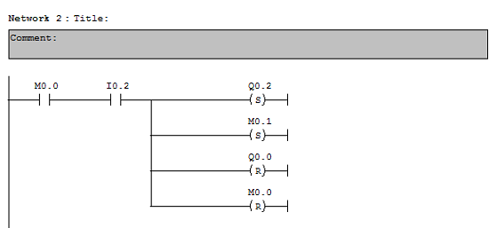
Step 2
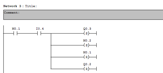
Step 3