#2 – Blinking an LED with Arduino
Hello Steemians, as I have said in #1 that my next post will be about blinking an LED. So here we go
The LED is a very common, infinitely useful component that converts electrical current into light. LEDs come in various shapes, sizes, and colors.
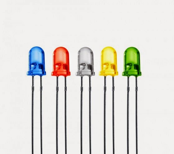
Connecting LEDs in a circuit takes some care, because they are polarized; this means that current can enter and leave the LED in one direction only. The current enters via the anode (positive) side and leaves via the cathode
(negative) side, as shown in Figure 3-7. Any attempt to make too much current flow through an LED in the opposite direction will break the component. Thankfully, LEDs are designed so that you can tell which end is which. The leg on the anode side is longer, and the rim at the base of the LED is flat on the cathode side.

When adding LEDs to a project, you need to consider the operating voltage and current. For example, common red LEDs require around 1.7 V and 5 to 20 mA of current. This presents a slight problem for us, because the Arduino outputs a set 5 V and a much higher current. Luckily, we can use a current-limiting resistor to reduce the current flow into an LED. But which value resistor do we use? That’s where Ohm’s Law comes in.
To calculate the required current-limiting resistor for an LED, use this formula:
R = (Vs – Vf) ÷ I
where Vs is the supply voltage (Arduino outputs 5 V); Vf is the LED forward voltage drop (say, 1.7 V), and I is the current required for the LED (10 mA). (The value of I must be in amps, so 10 mA converts to 0.01 A.)
Now let’s use this for our LEDs—with a value of 5 V for Vs, 1.7 V for Vf , and 0.01 A for I. substituting these values into the formula gives a value for R of 330 Ω. However, the LEDs will happily light up when fed current
less than 10 mA. It’s good practice to use lower currents when possible to protect sensitive electronics, so i’ll use 330 Ω resistors with my LEDs, which allow around 6 mA of current to flow.
Note: When in doubt, always choose a slightly higher value resistor, because it’s better to have a dim LED than a dead one! To know the value of a resistor when seen there are some color codes which I will give below, because the value for a resistor will not be written on it rather it will be given in colors.
Resistors
Reading Resistance Values
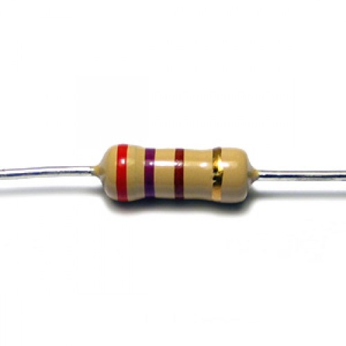
Resistors are very small, so their resistance value usually cannot be printed on the components themselves. Although you can test resistance with a multimeter, you can also read resistance directly from a physical resistor, even without numbers. One common way to show the component’s resistance is
with a series of color-coded bands, read from left to right, as follows:
First band Represents the first digit of the resistance
Second band Represents the second digit of the resistance
Third band Represents the multiplier (for four-band resistors) or the
third digit (for five-band resistors)
Fourth band Represents the multiplier for five-band resistors
Fifth band Shows the tolerance (accuracy)
The fifth band represents a resistor’s tolerance. This is a measure of the accuracy of the resistor. Because it is difficult to manufacture resistors with exact values, you select a margin of error as a percentage when buying a
resistor. A brown band indicates 1 percent, gold indicates 5 percent, and silver indicates 10 percent tolerance.
Starting from the left, the first and second stripes are coded according to this table:
Colour Value
Black 0
Brown 1
Red 2
Orange 3
Yellow 4
Green 5
Blue 6
Violet 7
Gray 8
White 9
The third stripe has a different meaning: It tells you how many zeros to add, like this:
Colour value Meaning
Black - No zeros
Brown 0 1 zero
Red 00 2 zeros
Orange 000 3 zeros
Yellow 0000 4 zeros
Green 00000 5 zeros
Blue 000000 6 zeros
Violet 0000000 7 zeros
Gray 00000000 8 zeros
White 000000000 9 zeros
The Solder-less Board
The solder-less board also known as breadboard is a plastic base with rows of electrically connected sockets. They come in many sizes, shapes, and colors.
The key to using a breadboard is knowing how the sockets are connected—whether in short columns or in long rows along the edge or in the centre. The connections vary by board.
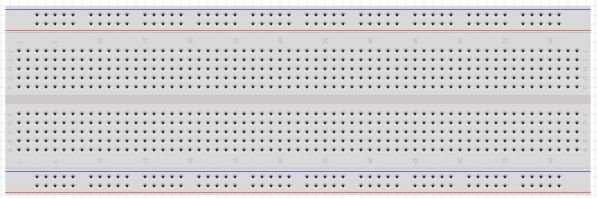
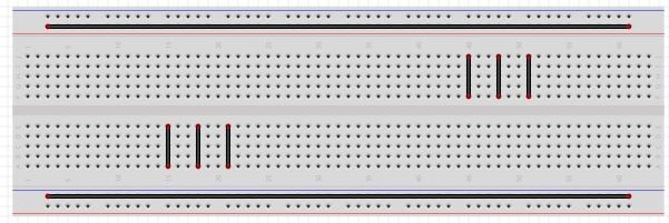
For example, in the breadboard shown above, columns of five holes are connected vertically but isolated horizontally. If you place two wires in one vertical row, then they will be electrically connected. By the same token, the long rows in the centre between the horizontal lines are connected horizontally. Because you’ll often need to connect a circuit to the supply voltage and ground, these long horizontal lines of holes are ideal for the supply voltage and ground. Often retailers who sell breadboard also sell small wires called connecting wires so as to minimize over-crowding of the breadboard.
Building our Project
Since all the pre-requisites needed for this project has been discussed (i.e. decoding resistors). For this project, I will be using a 330Ω resistor which is orange, orange, brown color code as shown below

Algorithm for this project
Here’s our algorithm for this project:
1. Turn on LED 1.
2. Wait half a second.
3. Turn off LED 1.
4. Turn on LED 2.
5. Wait half a second.
6. Turn off LED 2.
7. Continue until LED 4 is turned on.
8. Repeat indefinitely.
The Hardware
Here’s what you’ll need to create this project:
• Four LEDs
• Four 330Ω resistors
• One breadboard
• Various connecting wires
• Arduino and USB cable We will connect the LEDs to digital pins 2 through 5 via the 330-ohm current-limiting resistors.
Schematic Diagram
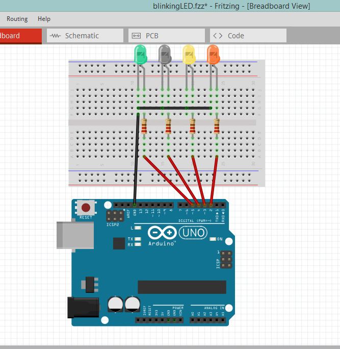
The software used for this schematic is called fritzing, it allows you to simulate your project before you start connecting.
The Sketch (Code)
Now for our sketch, enter the following code in the IDE:

In void setup ( ) the digital I/O pins are set to outputs, because we want them to send current to the LEDs on demand. We specify when to turn on each LED using the digitalWrite( ) function in the void loop( ) at the section of the sketch.
Running the Sketch
Now connect your Arduino and upload the sketch. After a second or two, the LEDs should blink from left to right and then back again. If nothing happens, however, then immediately remove the USB cable from the Arduino and check that you typed the sketch correctly. If you find an error, fix it and upload your sketch again. If your sketch matches exactly and the LEDs still don’t blink, check your wiring on the breadboard.
You now know how to make an LED blink with your Arduino.
Am a Systems Engineering Undergraduate interested in studying and making research about facts of life, which has been helping a lot in my field of study.
Kindly throw a follow @ebook-wizard to stay tuned for #3.