Building a timelapse slider rail with Arduino - Part 4 - Buttons, Power and Optocoupler.
Hey there,
This post goes into the final few parts of the hardware jigsaw that I needed in order to get together the final prototype of the time-lapse rail; buttons, power and optocoupler (no, that isn't a trio of superheroes).
Previous parts of the build are here...
https://steemit.com/photography/@markangeltrueman/building-a-timelapse-slider-rail-with-arduino-part-1
https://steemit.com/photography/@markangeltrueman/building-a-timelapse-slider-rail-with-arduino---part-2---stepper-motor-1510869489-2758267
https://steemit.com/photography/@markangeltrueman/building-a-timelapse-slider-rail-with-arduino-part-3-lcd-display
Buttons
Obviously, if you are going to have a menu system on an LCD then you need some way to navigate that menu system so the easiest way to do this is to use 4 buttons; Up, Down, Select and Back buttons cover all possibilities. The problem with using 4 buttons with the Arduino is that this could end up using 4 digital input pins, one for each button. This isn't ideal as I might need the pins for something else. However, there is a clever workaround
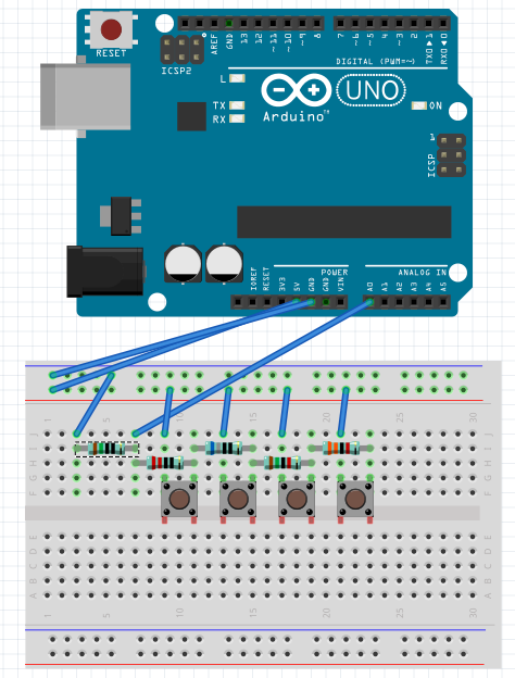
This implementation allows you to use one analog pin to determine which button has been pressed as each button has its own associated resistor. With all resistors being different, you get a different voltage reading on the analog pin when each button is pressed.
Here is a video of this working.
Power
A quick view of power.... Obviously, I don't want to have to cart a 5v power supply and a 12v power supply around with me, and this also all has to run from a single battery power source. I intend to use a 12v power source and then use what is known as a "buck converter" to pull off a 5v power supply from the 12v source. The 5v is used to power the Arduino, the other integrated circuits and the LCD. There are a few power considerations to take into account as well - turning the motor off when it's not being used and possibly turning the LCD off when the timelapse it taking place, but I'll go into those as I put all of these pieces together
This is what a buck converter looks like
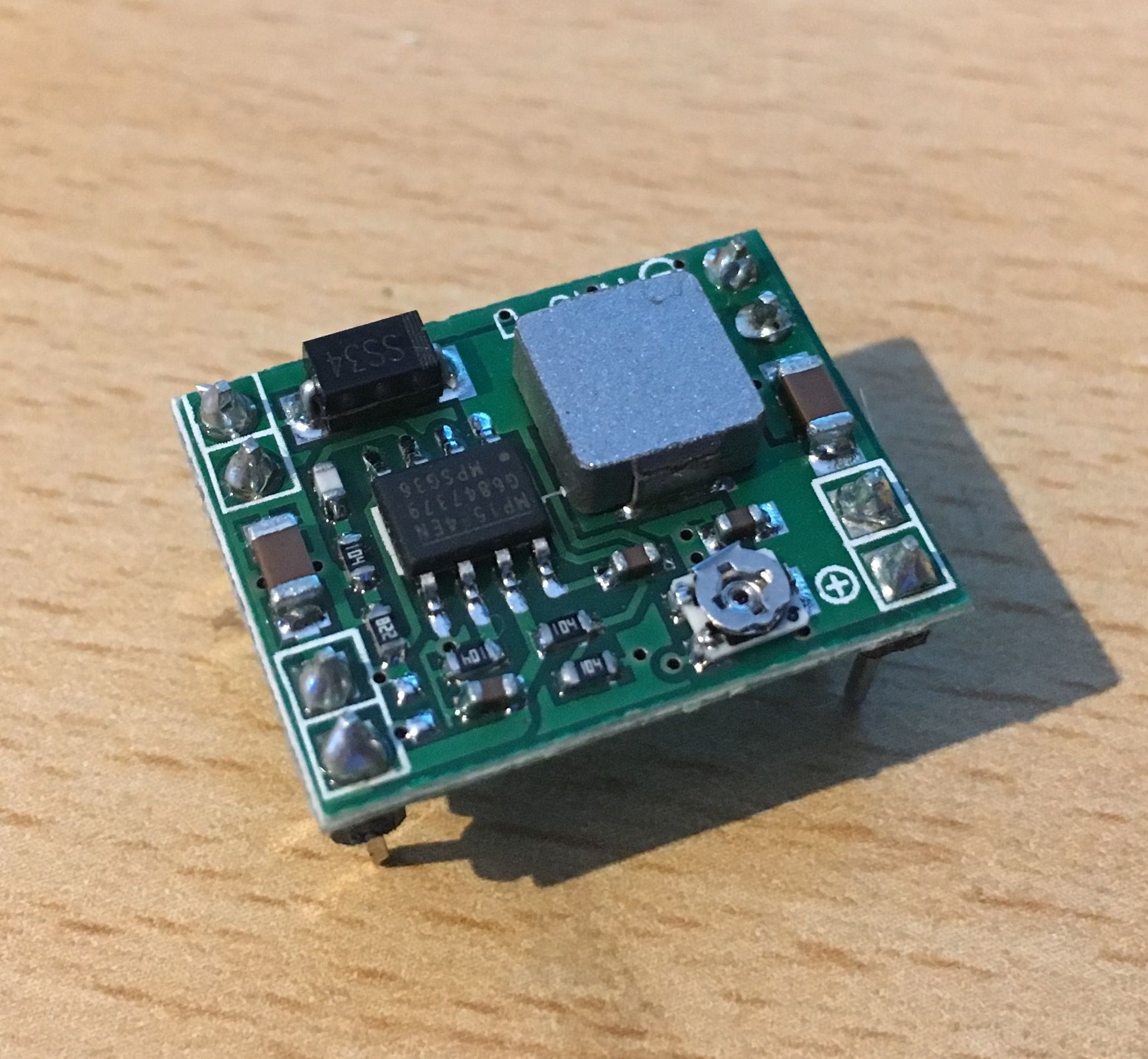
You basically turn the little silver potentiometer to adjust the output voltage. Really straightforward stuff.
Optocoupler
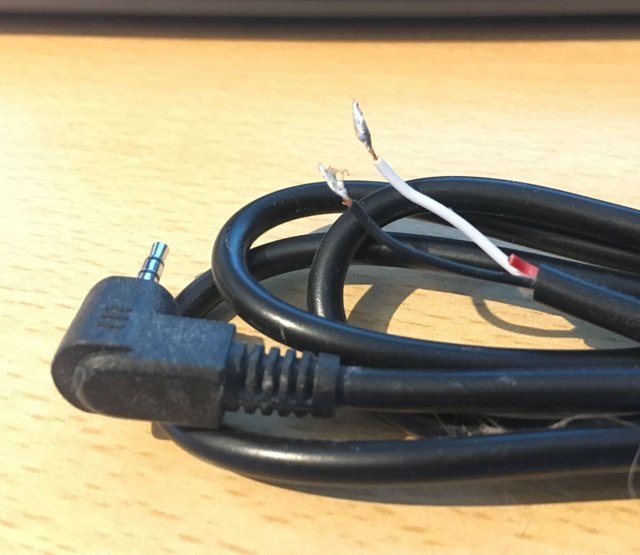
An optocoupler is basically a switch that you can control by giving it a high signal. I use one of these so that the Arduino can fire off the remote shutter on the camera. I have butchered a cheap ebay shutter release cable which I connect up to the optocoupler
Shorting the white and black cables in this image is what causes the shutter to fire when it's plugged into the remote release of the camera. You cant do this direclty from the arduino as the arduino only has the ability to sent 5v high signals and you cant be putting 5v into the camera when all you need to do is short the connections.
In the next post I should have all of these parts together and then will go through the menu options and hopefully get a working prototype up and running.
Thanks for looking
Mark
Looking forward to seeing the final product and what you can capture with it, thanks for the informative post @markangeltrueman
Cool stuff Mark!