How To Read A Digital Multimeter
A digital multimeter is an indispensable tool and a great addition to any professional technician workshop or tool collection. This tool is not only used to measure electrical parameters, test a battery but also used to check electrical circuit and diagnose electrical faults.
But how can you use or read a digital multimeter?
In this tutorial, I will show you how to read a digital multimeter (DMM) and cover how to take the basic measurements which includes voltage, current, and resistance.
Now let's begin.
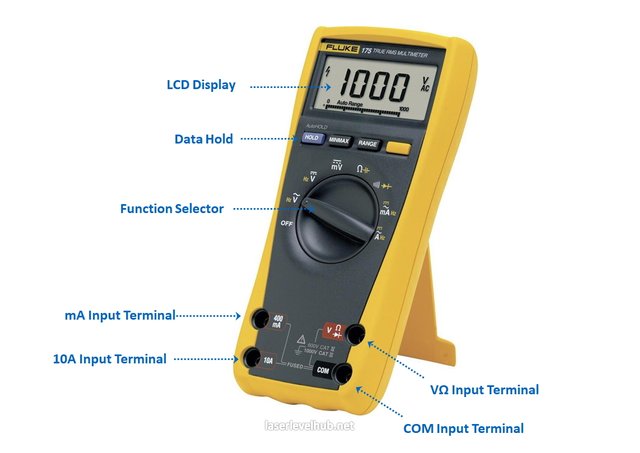
Parts Of A Digital Multimeter
A digital multimeter has three main parts which include:
- Ports
- Selection knob
- Display
Ports
The numbers of ports featured on a digital multimeter differ from one brand or model to the other.
Typically, a digital multimeter has three ports, and there are some that come with four ports. The two test probes are plugged into two of these ports based on the type of readings or measurement to be taken. The port labeled COM represent common and is mostly connected to the ‘-’ of an electrical circuit.
The black test probe is inserted into the COM port; this probe is not different from the red probe in the level of electrical conductance. Their color distinction is just to help you identify the probe for the positive and the negative charge of a circuit.
The port labeled 10A is used (connected to the red probe) when measuring currents that are greater than 200mA.
The third port, labeled mAVΩ is where the red probe is conventionally plugged into. With this port, you can measure voltage (V), current (up to 200mA), and resistance (Ω).
On the end of the probes is a banana type connector that plugs into the multimeter ports.
Any test probe with a banana type connector plug can be used on a multimeter, and this allows the compatibility of this meter with different types of test probes such as probes with:
- Banana to Test Probes: These are the common probes that come with a multimeter, they are not expensive and therefore easy to replace should you break one.
- Banana to Tweezers: Tweezers are useful if you want to test SMD components.
- Banana to IC Hook: This probe type works well on the legs of ICs and smaller ICs.
- Banana to Alligator Clip: This type of probes is good for connecting to pins or large wires on a breadboard. This probe is ideal for long-term tests and test that you don’t need to hold the test probes in position as you manipulate an electric circuit.
The display
A digital multimeter comes equipped with an LCD screen display to display its readings. It has four digits with the ability to display a negative sign.
And some meters comes with backlit feature for better reading and viewing under a very low light condition.
Selection knob
With the selection knob, users can easily set or select the parameter that they intend to measure with their multimeters, such as voltage (V), milliamps of current (mA), and resistance (Ω).
See also: Tips to Choose The Best Multimeter For Beginners
How to Read a Digital Multimeter
Read a Multimeter When Measuring Voltage
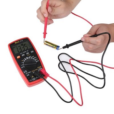
Let's start by measuring the voltage on an AA battery.
- Plug the red probe into the port labeled mAVΩ and the black probe into the COM port.
- Turn the selection knob to set your meter to “2V” in the direct current (DC) range (note that most portable electronics use DC (direct current) and not AC (alternating current).
- Connect the red probe to the ‘+’ or positive terminal of the battery and the black probe to ‘-‘ which is the earth or negative terminal of the AA battery.
Apply a little pressure on the probes to squeeze them against the negative and positive terminals of the battery and check the reading on your multimeter’s screen.
If you are using a brand new battery, you should see a reading that is around or slightly higher than 1.5 V on its display.
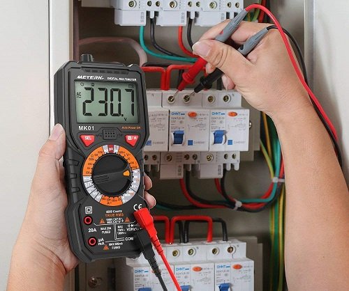
If you intend to measure DC voltage, you have to set the selection knob where V has a straight line that connotes DC voltage. AC voltage such as the one you’ll get from your wall socket can be very dangerous. For this reason, you will rarely need to use the alternating current setting on your multimeter.
If you are dealing with AC, I will suggest you get yourself a non-contact tester such as a clamp meter instead of using a digital multimeter.
What will happen if you switch the black and red probes?
Nothing bad will happen, the multimeter will simply provide a negative reading. The multimeter will measure the voltage in comparison with the COM probe. The amount of voltage on the ‘+’ of the battery in relation to the common or negative pin is 1.5V. When we switch the probe, the ‘+’ becomes the common or zero points. The amount of voltage on the ‘-‘ of the battery in relation to our zero-point will be -1.5V.
Generally, multimeters are not auto ranging, and you’ll need to set it to a range that it can measure. For instance, a range of 20V will measure voltage up to 20 volts and 2V up to 2 volts. So if you want to measure a battery of 12V or 5V, you need to set the meter to 20V range. If you set the range incorrectly, the multimeter screen will probably change, and you will see ‘1’ on your device’s display.
Overload
If you select a voltage setting that is lower than the voltage you intend to measure, what will happen to your meter?
Nothing bad.
Here, the meter will try to tell you that there is overload by displaying ‘1’ on the screen (since you are using it to measure a voltage that is higher than the range you selected).
When this happens, try switching to a higher range on the meter.
Learn more: Safety Tips You Should Know When Using a Digital Multimeter
How to Read a Digital Multimeter When Measuring Resistance
Resistors normally have color codes on them and if you don’t know what they stand for, it’s ok. There are a lot of calculators online that you can turn to and get the value.
But if you have no internet access, a multimeter is your go-to equipment for measuring resistance.
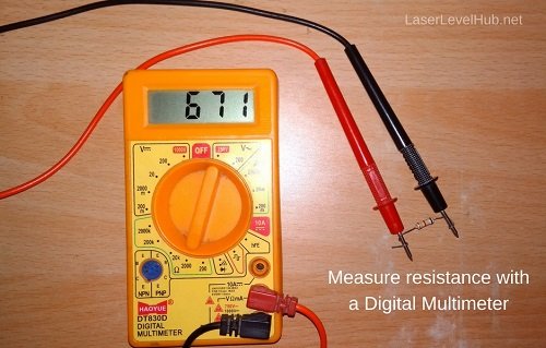
Set the meter to 20kΩ with the selection knob and then pick out a random resistor. With the probe in the same port as it is when measuring voltage, hold the test probe pins against the legs of the resistor.
The multimeter will read one of these three things; the actual resistor value, 1, or 0.00.
- If the meter reads 0.98, it means the resistor has a value of 980Ω or about 1kΩ (don’t forget that you set the meter to 20kΩ or 20,000Ω mode, so you have to move the decimal point three times to the right to get 980 Ω).
- In case you have the ‘0.00’ or zero on your meter, you’ll have to select a lower mode suck as 2kΩ Or 200Ω.
- If the meter display ‘OL’ or reads ‘1’, it is overloaded, and you have to set the meter to a higher mode such as 2MΩ or 200kΩ mode. There’s no cause for alarm; you only have to adjust the settings using your selector knob.
Note that some resistors have a 5% tolerance. The color code may indicate 10kΩ, and due to the inconsistency in the manufacturing process, a resistor of 10kΩ could be as high as 10.5kΩ or as low as 9.5kΩ. Not to worry, this resistor will work just fine as a general or pull-up resistor.
If we drop the knob down to a lower setting, 2kΩ, what would be the response of the meter?
The readings will change. The readings will show up on the display because the resistor (1kΩ) we are trying to measure is less than 2kΩ which we selected on the multimeter. There will be more digits displayed after the decimal point, and this provides a slightly higher resolution on our new reading.
What if we drop the meter to the next lowest setting (200Ω), is it going to damage the meter?
No, it won't. Here, the 1kΩ we are trying to measure is greater than 200Ω settings on the meter, we have overloaded the meter, and it will display ‘1’ on the screen to tell you that have to select a higher value.
It is rare to get a reading less than 1Ω when measuring resistance. Note that the value you get from your measurement may not be perfect as the temperature can meddle with the result of your readings.
It is also difficult to get the actual value of resistance when measuring a resistor that is physically installed in a circuit. The other components on the circuit board will affect the reading.
How to Read A Multimeter When Measuring Currents
Determining the amount of current flowing in a circuit is one of the most difficult and insightful measurements in the world of electronics. This is because you have to measure it in series.
While the voltage is measured by poking at the positive and negative point on the circuit (in parallel), you’ll have to interrupt the flow of current physically or break the circuit and put your multimeter in-line to measure current.
Pull out the ‘+’ wire going to the resistor to break the power to the circuit and then insert the multimeter in-line with the current path so that it can measure the current as it flows through.
Hold the multimeter in this position for a while and watch what happens to the system for a few minutes or seconds. You may not be convenient holding the probes while watching the system and may want to free your hands. In this situation, alligator clips probes can be very helpful.
After connecting the multimeter, you can now make the proper settings and measure the current. This process works similarly to measuring voltage and resistance using a multimeter – you have to select the right range. Set the dial to 200mA and start from there (this is because most breadboard project’s current consumption is usually under 200mA).
Make sure you plug the red test probe into the 200mA port while the black remains in the COM port. In some multimeters, the port labeled mAVΩ for measuring resistance and voltage is also labeled ‘200mA’. This means you can leave the probe in the same port and measure voltage, resistance, and current.
And if you suspect that the circuit may be consuming 200mA or above, switch the red probe to the 10A port for safety. Overloading the current can damage the meter or blow a fuse rather than displaying the overload warning on the screen.
When measuring current, your meter will act like a piece of wire; when you complete the circuit, it will power on. The multimeter should display the readings instantaneously. All multimeters will measure current over time and give you the average value, so you should expect fluctuations in the readings.
What happens if you switch probes?
Just like other measurements, the color of the probes does not affect the meter so nothing bad will happen to your multimeter. Only that the readings are going to become negative (and carry the ‘-’ symbol).
Once you are done taking the measurements, return the probes to the voltage port and set the meter back to DC voltage range if necessary.
Failure to do this before measuring voltage will get your meter to display ‘0.000’ on the screen to show you that there is no current flowing and within that split second, the fuse will blow off. That not good, but if you blow your fuse, you can unscrew the meter and replace the fuse.
Find out: Helpful Guides to Choose The Best Automotive Multimeter
How to Read a Digital Multimeter When Testing Continuity
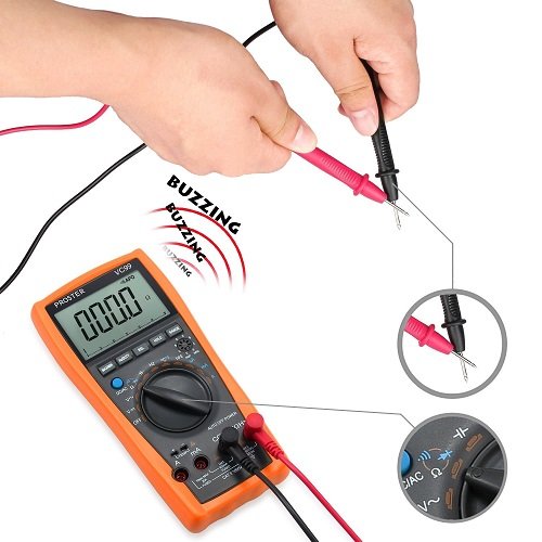
This involves testing the resistance between two points. If the resistance is very low, the two points are electrically connected, and the meter will emit a tone. If the resistance is a bit higher, then the circuit is open, and the meter will produce no tone.
The continuity test helps to ensure that the connections between two points are made correctly and also help to trace where connections have been made or not made.
Steps to test continuity
Turn the dial to the continuity mode (this mode may vary from one DMM to another, but you can look for a diode symbol and that of a speaker with waves coming out of it).
Touch the test probes with one another the meter should now produce a tone (note that some multimeter does not have the continuity settings). The sound is produced because there is a very low amount of resistance.
Now, turn off the system you want to test. Poke at two separate ground pins on the breadboard or the points you wish to check with the probes. Your multimeter should emit a tone.
And if not, you can use this to trace where there is a break in the line, breadboard, wire, or PCB. Your eyes may not see where if two SMD pins are touching, but with the help of a multimeter, you can easily figure it out.
Conclusion
Hope this article has opened your eyes to how to use or take readings with a multimeter? Multimeters are pretty easy to use, aren’t they? However, you have to select the best meter for you and follow the necessary safety measures to ensure your safety and make the most out of your multimeter.

Congratulations @brucerivers! You received a personal award!
Click here to view your Board
Congratulations @brucerivers! You received a personal award!
You can view your badges on your Steem Board and compare to others on the Steem Ranking
Vote for @Steemitboard as a witness to get one more award and increased upvotes!