PROPELLER VISION : An application of the phenomenon - "PERSISTENCE OF VISION".

It was the most fascinating project for me, now I would like to share the fascinating experience.
The PROPELLER VISION is based on the phenomenon called PERSISTENCE OF VISION and if you are not aware of what is Persistence of Vision, Please google it first because this is the fundamental idea that you must be having to go ahead with this project.
Here, the major question is, how the array of 8 or 12 LEDs will be able to represent a letter or word???
Yes, It was the first question that came to my mind when I thought about this project. While doing this project, keep this thing in mind that this project is all about what you see and not about what actually happens and that's why it is restricted to normal humans and not for those super natural creatures who are having a very low duration(in micro seconds) to retain an image in their retina. If you do not understand what I m talking about here, you will soon be able to understand, just be patient!!
Here as you see, if you have a board of LEDs consisting of 35 LEDs. You can easily show any number or alphabet, here number of columns for each alphabet is 5 and number of LEDs in 1 column is 7.


In my case it was somewhat different, I chose 12 LEDs and 9 columns, here in the above figure you can see 3 major parts of our projects.
(i) Microcontroller Board : This is the heart of this project, what it really does is, it provides very fast switching of LEDs that can not be done manually.
It consists of a Microcontroller(ATMEGA16) ,Voltage Regulator(7805), Diode, Switch, Resistors, Capacitors of suitable values. You can either make your own board or purchase one. Those who are not familiar with microcontrollers, may consider to purchase one. These are easily available online.

USB AVR PROGRAMMER

ATMEGA16 DEVELOPEMENT BOARD
(ii) IR Sensor Board: It helps to indicate the completion of one rotation. It's output is very important because program repeats itself after every rotation. It consists of Emitter , Receiver, Potentiometer, Comparator etc. or you may simply use Emitter , Receiver and nothing else.

IR SENSOR CKT BOARD
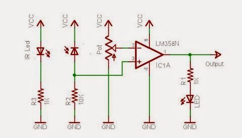
SCHEMATIC FOR IR SENSOR BOARD
(iii) Array of LEDs : Using suitable resistors, It can be made on any PCBs. Value of resistor used depends on colour of diode and of course on applied voltage.

ARRAY OF LEDs CONNECTED TO ATMEGA16 PORTS

DEEP PATEL WORKING ON LEDs
(iv) MOTOR : It is the fourth important part, I used induction motor because it's easy to use.

POWER SUPPLY ARRANGEMENT

MOTOR IN RUNNING MODE
As far as the power supply in the running mode is concerned, it is entirely up to your ease of operation. I had tried one more method for power supply using BEARINGS, but it failed because at very high RPM, bearings could not handle power supply. Here is the arrangement,

BEARINGS ARRANGEMENT FOR POWER SUPPLY
HOW IT WORKS??
Now let's understand the whole process. It starts with the power supply of 12v DC(or any, its up to you) which gives power to the Microcontroller Board, the board having a Voltage Regulator(7805) which steps down the voltage to 5V DC, the appropriate pin for input of IR SENSOR and appropriate ports for output of LEDs in the Microcontroller is then selected.
Now its time to calculate TIME DELAY, which is the most important calculation that we need to do prior to the programming. In our arrangement, we have an array of LEDs which is equivalent to single column, for showing a letter or a number we need 9 columns(in this case). Each letter is having some width hence each column must be having some width, that width is nothing but the duration of time for which the LEDs are ON, So TIME DELAY will be the duration of time for one column in our program.
SOME CALCULATIONS...
Suppose you have an induction motor of 1000 rpm,
so for one revolution time, T=(60/1000) sec = 0.06 sec
suppose the radius of the propeller is 20 cm,
circumference=(23.1420)=125.6 cm
let's assume the width of one column = 0.5 cm
number of columns = (125.6/0.5) ~ 251 columns
If one letter is made of 9 column then number of letters = (251/9) ~ 28 letters
Time delay for one column = (time for one revolution/no. of column)=(0.06/251) ~ 239 micro sec
suppose you are using an external crystal of 16 MHZ as a clock, then no. of cycles in 1 sec=16000000.
so, number of cycles in 239 micro seconds = (239*16000000)/1000000= 3824
Now we have calculated time for each column , so space between the letters can also be given by giving delay of 2 or 4 columns its up to you and here the space means all the LEDs are OFF.
Just to check all the electrical arrangements are correct before burning the microcontroller program, I connected all the LEDs to VCC in the microcontroller board and the motor to the AC(230 V) supply and see how it looked... AMAZINGGG....

here the RED circle in center is due to the LED in the microcontroller board, which is always ON.
Now its time for some programming..
//-----------------------------------------------------------------------------------------------------------
//Programmer: DEEP PATEL
//Target microcontroller: ATMEGA16
//-----------------------------------------------------------------------------------------------------------
#include<intrinsics.h>
#include<ioavr.h>
#include<stdio.h>
void bin(int a,int b,int c,int d,int e,int f,int g,int h,int i,int j,int k,int l)
{
PORTC = (((1)<<7) | ((1)<<6) | ((1)<<5) | ((1)<<4) | ((a)<<3) | ((b)<<2) | ((c)<<1) | ((d)<<0));

PORTA = (((e)<<7) | ((f)<<6) | ((g)<<5) | ((h)<<4) | ((i)<<3) | ((j)<<2) | ((k)<<1) | ((l)<<0));

}
int main() {
DDRA=0XFF;
DDRC=0XFF;
  while(1) {

   if(PINB & (1<<PB0))  {

     // case 'E'
{bin(0,0,0,0,0,0,0,0,0,0,0,0);} __delay_cycles(4500);
{bin(1,1,1,1,1,1,1,1,1,1,1,1);} __delay_cycles(4500);
{bin(1,1,1,1,1,1,1,1,1,1,1,1);} __delay_cycles(4500);
{bin(1,1,0,0,0,0,1,1,0,0,0,1);} __delay_cycles(4500);
{bin(1,1,0,0,0,0,1,1,0,0,0,1);} __delay_cycles(4500);
{bin(1,1,0,0,0,0,1,1,0,0,0,1);} __delay_cycles(4500);
{bin(1,1,0,0,0,0,0,0,0,0,0,1);} __delay_cycles(4500);
{bin(1,1,0,0,0,0,0,0,0,0,0,1);} __delay_cycles(4500);
{bin(1,1,0,0,0,0,0,0,0,0,1,1);} __delay_cycles(4500);
{bin(1,1,1,1,0,0,0,0,0,0,0,0);} __delay_cycles(4500);
{bin(0,0,0,0,0,0,0,0,0,0,0,0);} __delay_cycles(12000);
// case 'M'
{bin(1,1,1,1,1,1,1,1,1,1,1,1);} __delay_cycles(4500);
{bin(0,0,0,0,0,0,0,0,0,1,1,0);} __delay_cycles(4500);
{bin(0,0,0,0,0,0,0,0,1,1,0,0);} __delay_cycles(4500);
{bin(0,0,0,0,0,0,1,1,1,0,0,0);} __delay_cycles(4500);
{bin(0,0,0,0,0,0,1,1,1,1,0,0);} __delay_cycles(4500);
{bin(0,0,0,0,0,0,0,0,1,1,1,0);} __delay_cycles(4500);
{bin(0,0,0,0,0,0,0,0,0,1,1,1);} __delay_cycles(4500);
{bin(1,1,1,1,1,1,1,1,1,1,1,1);} __delay_cycles(4500);
{bin(1,1,1,1,1,1,1,1,1,1,1,1);} __delay_cycles(4500);
{bin(0,0,0,0,0,0,0,0,0,0,0,0);} __delay_cycles(12000);
// case 'I'
{bin(1,1,1,0,0,0,0,0,0,0,0,0);} __delay_cycles(4500);
{bin(1,1,0,0,0,0,0,0,0,0,1,1);} __delay_cycles(4500);
{bin(1,1,0,0,0,0,0,0,0,0,1,1);} __delay_cycles(4500);
{bin(1,1,1,1,1,1,1,1,1,1,1,1);} __delay_cycles(4500);
{bin(1,1,0,0,0,0,0,0,0,0,1,1);} __delay_cycles(4500);
{bin(1,1,0,0,0,0,0,0,0,0,1,1);} __delay_cycles(4500);
{bin(1,1,1,0,0,0,0,0,0,0,0,0);} __delay_cycles(4500);
{bin(0,0,0,0,0,0,0,0,0,0,0,0);} __delay_cycles(4500);
{bin(1,1,1,1,1,1,1,1,1,1,1,1);} __delay_cycles(4500);
      }

 }

 return 0;
}
After burning this program , it will show three letters... E M I.
I chose these letters you can choose any.
Here you can see I have used delay cycle of 4500 instead of 3824 , because it was suitable, calculations are just the approximations, in reality you need to adjust some values.
Please check out the below video which shows "GAURAV AND DEEP"
It was the joint effort from me, Gaurav, and my project partner, Deep.
Hope you liked !!
Please visit : https://gauravbarwalia.blogspot.in/ for more such cool experiments.